Hi
I could, but you probably won't be able to get the same elements as I did, which means you won't be able to make it to work. And if you don't understand how it works, you can be harmed (high voltages)
I think it would be best if you learned as much as possible as you can first and try to build one yourself.
When I will finnish working on it I will post PCB anyway so I think you should wait until then.
luka,where need swich 'clk_in ' cable in your smps schematic?And 4n33p optocaupler,which the same i use?Need use darlinkton?  ,or i can use normal: 4n25,4n27,4n35?And your smps works without feedback?When i switch without feedback smps not blow?thanks 🙂
,or i can use normal: 4n25,4n27,4n35?And your smps works without feedback?When i switch without feedback smps not blow?thanks 🙂Hi
That all "clk_in" business is not whole as I though it would be enough, I bring clock from my amp. Since amp's and smps's GND are not the same I will need another board with 6n137 or something like that for sync. of SG or I won't need nothing at all.
I think it would be even better if you don't use darlington opto.
My smps is now without feedback, don't have time right now to work on it. Of course it won't blow but it will be unregulated
Mr. LUKA
HI Dear
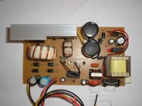
Thanks for all. I thing it´s a clear design. The power with this toroid and IGBT is around 230Watts OK?
Regards.
HI Dear
Thanks for all. I thing it´s a clear design. The power with this toroid and IGBT is around 230Watts OK?
Regards.
Re: Mr. Electromen
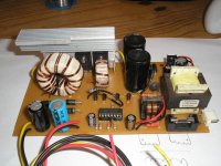
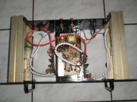
I wouldn't use that bridge rectifier for SMPS, most likely its slow 50-hz variety and causing heating and EMI problems with higher freq.
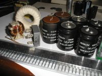
CHACALPOWERS said:Yesterday I built the SMPS inside my prototype power amplifier. I like it but I will build a next version so big. Here is a pic of six 10.000 uF/250V caps, 50 Amps bridge diode, input filter, and more components.
I wouldn't use that bridge rectifier for SMPS, most likely its slow 50-hz variety and causing heating and EMI problems with higher freq.
Re: Mr. Electromen
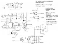
Are you sure you got your gate drive circuitry right? To me it looks like catastroph waiting for its turn.
(Hint: location of C12 and C13)
CHACALPOWERS said:The final design is mixing of various others, ok? Take a look in this:
Are you sure you got your gate drive circuitry right? To me it looks like catastroph waiting for its turn.
(Hint: location of C12 and C13)
Mr. LUKA
Dear Mr.
In this version not, ok? In another version it´s optozener regulated, with around +80/-80V wide open and +65/-65V under regulation. The number of turns of this version is 64 turns/primary (342VDC) and 15+15 turns secundary. In regulated version I don´t remember, but I think is 34 turns primary (342VDC).
Regards.
- Home
- Amplifiers
- Power Supplies
- Offline full-bridge SMPS… need help