Huh I have now 24, 11-0-11.Primary: first 0.5 of primary, sec, second 0.5 of primary.
When pluged in 230ac trafo produces low freq. hum.I think that is because of that many turns in sec
When pluged in 230ac trafo produces low freq. hum.I think that is because of that many turns in sec
luka said:Huh I have now 24, 11-0-11.Primary: first 0.5 of primary, sec, second 0.5 of primary.
When pluged in 230ac trafo produces low freq. hum.I think that is because of that many turns in sec
You said you do not use this zenners on that schematics of yours: THEN of aditional winding on maim ferit powers the controleer: HOW the circuit starts when MAIN FERIT is not working yet?
Transformer design
Luka
The number of turns for a transformer using a ETD-49 core set
for EEU power single phase at a FSW of 50kHz and a 340VDC
in for a halfbridge with a 35 VDC out would be:
340 x 10^8 / (4 x 2800 X 50000 x 2.11) = 28 Turns
and the secondary would be:
1.1 x (35 + 2) x 28T / (252 x .95) = 6 turns each side of center tap. 28 - 6 - 0 - 6.
You can verify this roughly by Vin x (NS/NP) where Vin = 340VDC and NS = 6 and NP = 28.
The value at the input of the output inductor will be about 76 volts
which is about right 2 X Vout = 70 volts therefore the end to end voltage across the secondary would be 152 volts for an end to end load voltage of 70 volts.
The above was calculated using the methods in Browns book.
chas1
I don't know from where you got 76v on inductors input. This voltage won't simply stop there, if there is not large current drawn by the load to make 31v of drop on inductor.
Can you explain that part?
Can you explain that part?
The previous calculations assume proper duty cycle control in order to achieve the desired output voltage. Effectively, the duty cycle tends towards zero as load current is reduced to zero and continuous conduction mode is abandoned, leading to chaotic operation (harmless) and pulse skipping below a certain current level. A small dummy load is recommended.
Eout
Luka
The Eout of any supply is designed around the the inductor in the CCM and to prevent DCM, if the inductor runs dry in most cases regualtion becomes a nightmare because of the frequency change and the poles and zero's change in the compensation
loop. A good design always operates close to the steady state of the supply. Eva has answered you question throughly. You should notice most commerical products have a constant Rout and in mine you will see that is about 5k on each rail.
chas1
Rout
Luka
The load I used is based on my supply, 50VDC per rail with a an output filter of 210uH inductor and 840uF capacitor to ground (center tap of secondary) and this was only to test the design and will change with the end product. As you might have guessed the controller is on the secodary side and will be powered by a low voltage power supply. I will not have to worry about startup and grounding problems, this will make the supply more robust after all it will be the heart of my amplifier and I don't want to damage the amp because of a supply. Browns book does a good job in describing the design of all parts of a supply even though it has a few error's and if you make reference to it, work thru his examples you will end up with a good design in a short period of time. Along the way compare his methods to your other reference's .
chas1
I have tested half-b. with renewed 24-7-0-7 trafo.Even if it does not have correct turns,it works great.I also tested it.It put out 200Vp-p.That was with both sec used.Load was 30 ohms and waveforms are 97% of perfect square.
200Vp-p is still OK,right, for -/+35v ouput?
200Vp-p is still OK,right, for -/+35v ouput?
Secondary side along with feedback loop
Luka
Good, I am glad that you have some postive results. I would like to see your secondary side schematic along with the feedback loop that would help answer your question, but a rule of thumb about output voltage is the voltage at the input to the inductor after the rectifiers should be about twice the output voltage. The turns ratio of my transformer is identical to yours but my design could support 60 volt rails but I regulated that down to 50 volts for testing. I believe you can remove one turn on your secondary, maybe two. The inductor input for a +/- 35 volt output should be
about 75 to 80 volts or 160 volts across secondary.
😎
chas1
well there is not much to see.I have secondarys connected to 2 diods and 2 caps(just to get the DC).There is none inductors for now.
Feedback is made (for now) of potenciometer and optocoupler.It is voltage mode.
Could you explain the main diffrence betwen current and voltage mode?They can both have current limiting.
Feedback is made (for now) of potenciometer and optocoupler.It is voltage mode.
Could you explain the main diffrence betwen current and voltage mode?They can both have current limiting.
unreg?
Luka
You can test your supply with an amp in the unregulated mode by grounding pin 1 of sg3525 and tying pin 2 directly to pin 16. I sugest that your output caps are rated at least 200VDC. Then connect your 30 ohm load to both rails ( make sure both rails are balanced with an equal load). You can get an idea of what your output rails will be at 50 % duty cycle and tailor you feedback components for the output you need. If you are sure you amp can be powered safely with the unregulated output voltage, fuse the outputs with 2 amp fuses and use a variac and slowly bing up the output, assume you reach +- 35 volts at load ( 8 or 4 ohm spk) measure variac output and then with a input of about 1V to amp @ (some freq) measure rails and variac output again, there should be a drop in the rails because the supply is not regulated then re-adjust variac so rails are at +/- 35 volts, you should have ample head room with your turns ratio, measure the variac again. If the variac output is below 220 VAC then you have more turns in secondary than you need and you might want to remove some windings in the secondary because after regulation you will droping the excess voltage thru the regulation of the supply as wasted power. No different than a linear regulator, but lets say your overhead is 10 volts or so this might be ok. You have to be the judge. The input power of a halfbridge will be about 3 times the rated output power. A few amp manufacturers use unregulated supplies, the transformer design is one of the keys to this method.
As for the difference between current mode and voltage mode read Pressman's explaination in the begining chapter on current fed and and current mode topologies it is explained in simple terms.
If you are asking about load protection you can design it into both current mode and voltage mode control and I think it works equally as well in both IMHO. You can use all the methods used in linear regulators to protect loads but I think montoring the primary current along with crowbars and overvoltage protection on the outputs should be sufficent IMHO.
chas1
Test
Luka
It escaped me in your post where you indicated that two rectifiers were driving your output caps, I think you might want to drive a bridge with center tap at ground with the outputs to the capacitors. if you refer to my last post inductors are not necessary in an unregulated supply since the caps supply the load during the off time which is about the same as the on time (50% DC). The supply should drive the amp with no problems and there should be liitle or no discoloration of the sound caused by the supply provided the caps are sized correctly. It would help if you supply the schematic of your output circuit you are using for test.
chas1
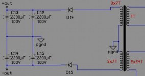
Today I did yet another test, this time with 2 inductors on same core, in front of the diodes.This is what I've got:
Vdc no load =>100V
Vdc with 22 ohm load => 85V
That is 330w of power dissipated in load.Is this ok?It is unreg., so is this to much voltage drop?
Vdc no load =>100V
Vdc with 22 ohm load => 85V
That is 330w of power dissipated in load.Is this ok?It is unreg., so is this to much voltage drop?
- Home
- Amplifiers
- Power Supplies
- Offline full-bridge SMPS… need help