With a 4 inch driver, off axis response starts suffering somewhere around 5khz. But what if in it's place 4 2inch drivers were used covering approximately the same footprint. If each of those drivers off axis response rolls off around 10khz, would it matter that you have 4 of them in a square pattern? I've heard that off axis response rolls off because of the phase difference between the close edge and the far edge of the driver, but it doesn't seem to me that 4 2 inch drivers would roll off at 5khz but that they would still roll off at 10khz off axis
The array of smaller drivers would have approximately the same effective diameter as the larger driver and the off-axis roll-off would be similar.
You can model this with Tolvan Edge:
Tolvan Data
You can model this with Tolvan Edge:
Tolvan Data
Member
Joined 2003
Because the bulk of the radiating area is further from the center point than a single 4", the 4-square 2" arrangement will roll off at a lower frequency off-axis than a single 4" driver. You can run a simulation to verify.
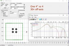
As Juhazi has shown in the above attached thumbnail, you can easily do this kind of "what if" scenario using "The Edge", a diffraction modeling program. You can add any number of drivers, choose the number of corners in your baffle and adjust the shape (e.g. any convex N-sided panel can be modeled) and then move the "listening axis" (called the "mic") around to see the off axis response. Closed and open-baffle systems can be modeled, and the results are pretty close to reality but don't include boundary interactions (e.g. with the floor, ceiling, and walls of the room).
The Edge is very good for testing out driver layouts and such before cutting wood. I use it often when planning my own projects.
The Edge is very good for testing out driver layouts and such before cutting wood. I use it often when planning my own projects.
Hi,
You have to realise the effective radiating area of a driver
decreases above the piston motion frequency so 4 2"drivers
spaced 2"(C to C) apart will be far worse than a single 4".
rgds, sreten.
You have to realise the effective radiating area of a driver
decreases above the piston motion frequency so 4 2"drivers
spaced 2"(C to C) apart will be far worse than a single 4".
rgds, sreten.
The Edge dos not simulate that "narrowing" of radiating surface, it's radiator is planar and rigid.
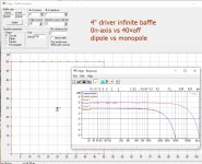
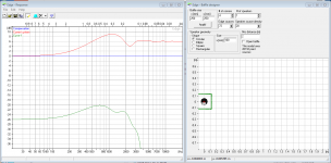
Four 2-inch drivers can not be placed so tightly to compare the diameter of the diaphragm of a single 4" driver. Here a sim with four 2" drivers vs one 4"
Four 2-inch drivers can not be placed so tightly to compare the diameter of the diaphragm of a single 4" driver. Here a sim with four 2" drivers vs one 4"
Attachments

The Edge dos not simulate that "narrowing" of radiating surface,
it's radiator is planar and rigid. Four 2-inch drivers can not be
placed so tightly to compare the diameter of the diaphragm
of a single 4" driver. Here a sim with four 2" drivers vs one 4"
Hi,
What you say is true, but it does illustrate the interference
of 4 separate sources, compared to a single driver.
In reality the "narrowing" of radiating surface will mean the
single 4" has better off axis, whilst the interference of the
4 separate 2" sources will be largely very much the same.
rgds, sreten.
I used 2 x 4" full range drivers vertically stacked (5" frames) and I used pennies to get them lined up sitting 10' away. To me 2x4" would be say an 9-10" driver across (due to the frame), and an 8" goes down to 90 degrees dispersion above 2khz, then even narrower above that (or less highs).
Now the vertically stacked 4 x 2" driver would have better side to side dispersion, but have the same vertical dispersion as 2 x 4" (assuming no frame also).
I think there was a speaker from "7th veil" that used vertically stacked 4 x 2" bandor drivers with a woofer module.
Now the vertically stacked 4 x 2" driver would have better side to side dispersion, but have the same vertical dispersion as 2 x 4" (assuming no frame also).
I think there was a speaker from "7th veil" that used vertically stacked 4 x 2" bandor drivers with a woofer module.
IMHO, The Edge does not do an appropriate job of simulating the interference from multiple drivers. I was able to show this on a different thread, where, The Edge's big brother, BASTA, produced simulation results that were a closer match to actual measurements.
As long as the radiation is omnidirectional and the center to center distance is smaller than about 1/2 wavelength at the radiating frequency, you will get full in phase addition. As the frequency increases, you will get phasey behavior. But with 2" drivers packed closely together, I would imagine it would start pretty high. Maybe 10 kHz? Listening distance also matters. You get less peaks and nulls the farther away you are. So, in other words, it's complicated. But I would guess the results will be nowhere as horrid as shown in the simulations above.
Why don't you build and measure?
The only difference is that BASTA uses actual measurement data rather than assuming a rigid planar radiator, correct?IMHO, The Edge does not do an appropriate job of simulating the interference from multiple drivers. I was able to show this on a different thread, where, The Edge's big brother, BASTA, produced simulation results that were a closer match to actual measurements.
Therefore both programs are going to be inaccurate unless you have the off-axis measurement data of the speakers in question.
Edge is still useful for 'what if' scenarios - i.e. if you put a couple of 4" woofers together and you see a huge null at 5kHz, perhaps that isn't the greatest idea to pursue.
I had mentioned in the dipole diffraction thread that I noticed the EDGE includes a Cos(angle) term in the directivity of all sources.IMHO, The Edge does not do an appropriate job of simulating the interference from multiple drivers.
This is appropriate for dipole sources, but not monopole sources.
http://www.diyaudio.com/forums/mult...ffraction-dipole-radiation-9.html#post4249318
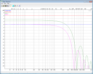
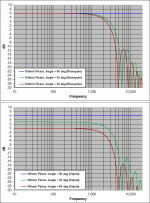
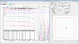
For example, here is what EDGE gives for a 100mm circular piston on a HUGE baffle (ie minimal diffraction contributions) for mic angles of 0deg, 45deg, and 60deg. Compare with the plots of theoretical piston dispersion with and without the Cos(angle) term included. You can clearly see the effect of the Cos(angle) term is included in the response of the EDGE monopole sources
Perhaps this is the source of the issue you are having when simulating multiple drivers off-axis.
I also notice at angles > 30deg you need to use a fairly high point density on the piston to perfectly match the ripples in the roll-off with theory for a flat circular piston.
Attachments
Ehem, a huge baffle will not show dipole character at all! Not in reality nor in simulation!
Also mic distance makes difference with off-axis modelling, eg 1m is too short for a wide baffle.
Also mic distance makes difference with off-axis modelling, eg 1m is too short for a wide baffle.
I agree, that was the whole point of my post.Ehem, a huge baffle will not show dipole character at all! Not in reality nor in simulation!
The EDGE simulator incorrectly adds a dipole character, ie Cos(angle), to all sources.
As long as the mic isn't positioned too far off-axis, the error is not large.
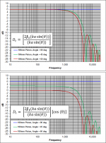
The EDGE simulation I had posted was for a 100mm circular piston centered on a 500m x 500m baffle, with the "Open baffle" check box un-selected. The baffle is large enough that edge-to-mic distance makes the edge diffraction contribution to the overall response quite small. So, with mic positioned 2m from the source, simulation should show directivity response for a piston in an infinite baffle. In other words, it should match the upper theory plot. However, it doesn’t match the upper plot. It matches the lower theory plot which includes a Cos(angle) term.
Attached pic clarifies the directivity equations that were plotted.
Attachments
Last edited:
I'm a little confused as to where the cos (theta) angle arises from. Isnt the magnitude lower with the cos (theta) because at an angle if your mic distance is still 2m, the actual distance to the mic is further because it's no longer perpendicular to the driver. So for example if at 45 degrees, then it would be 2m away in the z but also 2m away in x for example so it would be ~2.8m away total accounting for the lower measured output? I don't see why the cosine necessarily means it's approximating like a dipole it just seems to account for the extra distance to me.
Also thank you for the answers from everyone! I've been really busy but didn't even think to mess with edge to look at this question!
Also thank you for the answers from everyone! I've been really busy but didn't even think to mess with edge to look at this question!
Your plot looks correct to me for 40deg off axis (ie showing the cos(angle) error), just a bit of “fuzz” on the curve due to the baffle edge contribution.I could not get that difference with just 50m (164ft) per side baffle, mic at 2m.
6dB + 20*log[Cos(40)] = 3.7dB
Your thinking is correct that SPL level changes with distance would have an effect as well.Isnt the magnitude lower with the cos (theta) because at an angle if your mic distance is still 2m, the actual distance to the mic is further because it's no longer perpendicular to the driver. So for example if at 45 degrees, then it would be 2m away in the z but also 2m away in x for example so it would be ~2.8m away total accounting for the lower measured output?
To avoid this, you need to hold distance to source constant when varying angle. (ie for 2m @ 45 degrees, x = 1.414m, z = 1.414m)
However, the EDGE software normalizes the response by the on-axis SPL level for the same mic distance.
So, in effect, holding constant distance is taken care of for you.
Here is another example to help illustrate the Cos(angle) error/problem with EDGE.
If we take the Juhazi example 50m baffle and place the mic offset by x =2m and then vary z you will get the attached trends. Notice that as the mic is moved closer to the baffle the distance between mic and source is getting smaller but the overall level is reduced rather than increased due to the Cos(angle) term.
Bottom line, to avoid this error make sure angle between the mic and any source point is < 15 degrees.
Attachments
Hey, with Edge, when we simply just move the mic sideways, the distance to mic gets longer just like maggiesnsmacs said. I know that and I know that it makes dB drop. I did not change distance in my previous examples.
Of course we should deminish distance to baffle accordingly to cos to maintain source-mic distance constant! (If we want to be precise with dB)
But that should not affect dipole-monopole difference.
Of course we should deminish distance to baffle accordingly to cos to maintain source-mic distance constant! (If we want to be precise with dB)
But that should not affect dipole-monopole difference.
Last edited:
Of course we should deminish distance to baffle accordingly to cos to maintain source-mic distance constant! (If we want to be precise with dB)
Since EDGE normalizes the response relative to on-axis SPL at the same distance, this is unnecessary.
From the documentation:
“The response is normalized so that the sum of all driver sources corresponds to 0dB if they had been located at the same distance to the mic.”
The +6dB SPL level comes from the source radiating into half-space above the baffle step transition frequency.
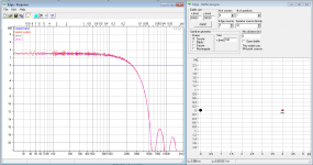
Try plotting response with your 50m baffle and mic placed at 45 degrees at three different distances(x=1m, z=1m), (x=2m, z=2m), (x=4m, z=4m). You will get the exact sample response (ignoring the minor fuzziness due to baffle diffraction) even though distance to the mic is varying from 1.4m to 12.6m, and you would expect an SPL shift of nearly 10dB. The response curves for the 3 distances lay on top of each other because EDGE is normalizing the response for you. (see Attachment #1)
I think perhaps the use of a large baffle is causing confusion. All discussion and examples are for monopole sources only.But that should not affect dipole-monopole difference.
I thought it would simplify things by only looking at the monopole piston contribution to the SPL without the diffraction effects by using a very large baffle.
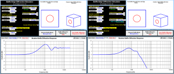
Perhaps a direct comparison between EDGE and BEDS for a 100mm circular piston centered on a 250mm x 250mm baffle will help clarify this issue with EDGE for monopole sources at off-axis angles.
Attachments #2 shows the BEDS results for on-axis and 87 degrees off-axis.
As expected from theory and experimental results, the low frequency SPL is essentially at the same level for both angles.
Attachments #3 shows the EDGE results for on-axis and 87 degrees off-axis.
Note that the low frequency SPL is down in level by -26dB for the off-axis angle relative to the on-axis.
This is not correct, and is the error I have been trying to draw attention to.
Attachments
The Edge normalizes FIRST measurement to 0dB below baffle step. If I move the mic out and replot , dB is lower etc. Works for me. But if I close and open Edge between simulations, normalization happens again.
Well, we must remember that Edge is just a very simple toy. Basta, BEDS etc. are more complex and versatile systems.
Well, we must remember that Edge is just a very simple toy. Basta, BEDS etc. are more complex and versatile systems.
- Status
- Not open for further replies.
- Home
- Loudspeakers
- Multi-Way
- Off axis response of multiple drivers