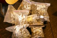
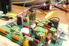
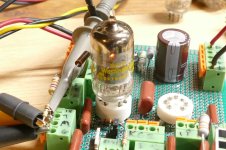
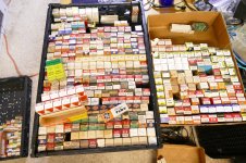
I have been working on a gain stage / driver circuit that is capable of delivering 100 volts peak-to-peak or more at a very low distortion level. The circuit is such that it will work with dozens of different tube types with minimal changes, just two resistor values. The test board has a 7 pin socket and a 9 pin socket wired in parallel so that I can try lots of different tubes. I have been going through my tube collection trying anything that will electrically fit either socket and taking data on what works and what does not. I had over 100,000 tubes thirty some years ago, but many have been sold, traded, given away or trashed over the years. There are still thousands of tubes in bags, and some boxed tubes in trays. I have a list of over 60 type numbers that will work in my test board, and I recently started testing some of the tubes in the board. I am now on my third 7 pin socket having run several hundred tubes through the first two.
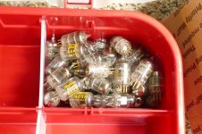
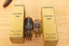
Yesterday I came across a pair of boxed tubes with a rather strange label on the box. This is brand recognition at its best....NOT! I introduce the new "GUARANTEED ELECTRON TUBE." It appears to be guaranteed to be a "Used" or "Factory Second" tube. Not necessarily a good tube. Both are "TRU-Vac" brand, and even that is not "TRU." The 6CB6 on the left does work and produces some good THD numbers, sometimes. It is highly microphonic and will exhibit a G1 to G2 short whenever it wants to. A whack with a pencil triggers the short or clears it. The little 6AK5 lights up purple, gets real hot and outputs no signal, or random noise. Its vacuum is not very TRU as its getter is nearly gone. If I find any more of these boxes, the tubes will be "tested" before disposal!
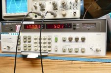
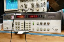
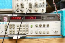
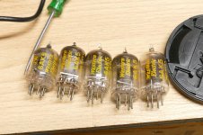
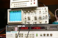
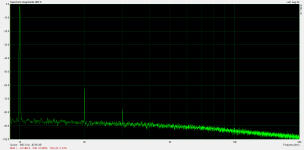
Many tube rollers believe that tubes with yellow ink on them are better than others with the same type numbers. Previous testing with WE 417A's up against Raytheon 5842's show that this may have some merit as the WE's consistently beat the Raytheon's in THD testing, but they are slightly different tubes, despite some WE's wearing both type numbers. I have found 5 WE 6AK5's in a random handful of about 50 assorted used 6AK5's which were pulled from a much bigger bag. Note that the tube on the right has very little getter left. It has likely seen a lot of use. How well does it work? How about 0.148% THD at 35.7 Vrms (100 V p-p). The other four WE tubes all showed THD's under 0.2%. I have run a few hundred used 7 pin tubes through this board to test them. The scope screen shows two traces, the input and output signal after the level knob on the output trace was adjusted to overlay the two traces with a new tube. I tossed any tube that did not produce a THD level under 0.4% or when the two scope traces showed an abnormal gain or significant trace deviation when whacked with a pencil.
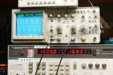
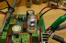
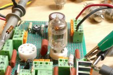
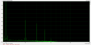
The circuit also works with the usual 9 pin TV IF amp tubes like the 6EJ7 / EF184. It is seen here with a 6KT6 in the hot seat making 0.169% THD. I have a lot more tubes to test.
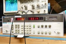
During the development of this circuit, I saw a low of 0.0699% THD on one little 7 pin tube. When cranked to 50 Vrms (141 Vp-p) the THD went to 0.514%. The residual THD of my old HP204D oscillator is 0.04% at 1KHz. It is the better of two identical oscillators.
Before anybody asks, yes, I have stuffed two tubes into the board at the same time. Nothing bad happens, but the result is not worth photographing, just some so-so numbers with no smoke. So far, the only unexpected effects were some verbal outbursts from accidentally touching the tab on the mosfet while hot swapping tubes.
Yesterday I came across a pair of boxed tubes with a rather strange label on the box. This is brand recognition at its best....NOT! I introduce the new "GUARANTEED ELECTRON TUBE." It appears to be guaranteed to be a "Used" or "Factory Second" tube. Not necessarily a good tube. Both are "TRU-Vac" brand, and even that is not "TRU." The 6CB6 on the left does work and produces some good THD numbers, sometimes. It is highly microphonic and will exhibit a G1 to G2 short whenever it wants to. A whack with a pencil triggers the short or clears it. The little 6AK5 lights up purple, gets real hot and outputs no signal, or random noise. Its vacuum is not very TRU as its getter is nearly gone. If I find any more of these boxes, the tubes will be "tested" before disposal!
Many tube rollers believe that tubes with yellow ink on them are better than others with the same type numbers. Previous testing with WE 417A's up against Raytheon 5842's show that this may have some merit as the WE's consistently beat the Raytheon's in THD testing, but they are slightly different tubes, despite some WE's wearing both type numbers. I have found 5 WE 6AK5's in a random handful of about 50 assorted used 6AK5's which were pulled from a much bigger bag. Note that the tube on the right has very little getter left. It has likely seen a lot of use. How well does it work? How about 0.148% THD at 35.7 Vrms (100 V p-p). The other four WE tubes all showed THD's under 0.2%. I have run a few hundred used 7 pin tubes through this board to test them. The scope screen shows two traces, the input and output signal after the level knob on the output trace was adjusted to overlay the two traces with a new tube. I tossed any tube that did not produce a THD level under 0.4% or when the two scope traces showed an abnormal gain or significant trace deviation when whacked with a pencil.
The circuit also works with the usual 9 pin TV IF amp tubes like the 6EJ7 / EF184. It is seen here with a 6KT6 in the hot seat making 0.169% THD. I have a lot more tubes to test.
During the development of this circuit, I saw a low of 0.0699% THD on one little 7 pin tube. When cranked to 50 Vrms (141 Vp-p) the THD went to 0.514%. The residual THD of my old HP204D oscillator is 0.04% at 1KHz. It is the better of two identical oscillators.
Before anybody asks, yes, I have stuffed two tubes into the board at the same time. Nothing bad happens, but the result is not worth photographing, just some so-so numbers with no smoke. So far, the only unexpected effects were some verbal outbursts from accidentally touching the tab on the mosfet while hot swapping tubes.
Attachments
-
 P4070523.JPG417.2 KB · Views: 284
 -
 P4020535.JPG403.8 KB · Views: 247
 -
 P4020472.JPG416.3 KB · Views: 221
 -
 P4020473.JPG355.9 KB · Views: 205
 -
 P4020471.JPG338.1 KB · Views: 209
 -
 P4070428.JPG407.9 KB · Views: 223
 -
 P4070427.JPG387.5 KB · Views: 234
 -
 P4070510.JPG408.8 KB · Views: 223
 -
 P4070445.JPG454.1 KB · Views: 235
 -
 P4070528.JPG648.6 KB · Views: 239
 -
 P4070520.JPG297.8 KB · Views: 236
 -
 P4070484.JPG441.2 KB · Views: 237
 -
 P4070447.JPG402.8 KB · Views: 240
 -
 P4070442.JPG407.9 KB · Views: 229
 -
 P4070444.JPG398.5 KB · Views: 231

I created a circuit for a guitar amp that I called the Saturator. It is basically a pentode stage with a bootstrapped load resistor so it sees a very high load impedance. Since the gain in a pentode stage is dependent on Gm and load impedance, use a lot of both of them and you get a LOT of gain. V/V gain of greater than 1000 can happen though realistic useful numbers are lower than that due to the microphonics created with three wound grids in a bucket full of gain.Is this an offshoot of Unset or something different?
The UNSET circuit applied "Schade" type feedback directly from the plate to the control grid of a pentode, while driving the cathode. This makes triode curves with a pentode tube and allows for a different screen supply so that TV sweep tubes can be run in a "simulated triode" mode.
Thinking from a guitar amp perspective I decided to put both circuits together if for no other reason than a variable gain stage that went beyond 11. I called this monster the UNSETURATOR. I built a breadboard with plug-in blocks (the green and orange things) for most of the components so I could tinker and tweak on it. It has turned into a very low distortion gain block in this iteration. My next move is to trace what this has morphed into and make a schematic before I mess it up.
Why would that be unexpected? 😎the only unexpected effects were some verbal outbursts from accidentally touching the tab on the mosfet while hot swapping tubes.
pentode cathodyane phase inverter.....sylvania 6ej7or janphilips 6ej7.good sound but cant find circuit . 6ej7 can drive gm70.
Last edited:
I was looking at low-distortion drivers for a Unity-Coupled amp and experimented with CCS-loaded pentodes with local feedback (p-channel fet driving shunt feedback network). The distortion was really low and the bandwidth was pretty wide too. I think it was 3dB down at 400kHz or something. It's impressive what you can do if you maximize gain and then use that gain to reduce distortion.
How much closed-loop gain are you getting with the really low distortion?
How much closed-loop gain are you getting with the really low distortion?
I just measured the level on the audio oscillator used in last night's experiments that was used to get 100 volts P-P out of the board with a 6AK5 in the socket. The closed loop gain was about 60 V/V. This is set by the feedback resistor ratios, the plate load resistor, and the bootstrap shunt resistor. All have been tweaked several times since the test board was built. I currently have the test board out of the circuit in order to trace its schematic. The board has been tinkered with so much over several months that I'm not sure what's in it now.
CAL sticker.... 10-93..... ;-D
All of those tubes... reminds me of '90 when we got rid of the tube supplies in our metrology lab. Must have been thousands.
I took home some very good ones for my preamp and amp at the time. 12AX7s, 12AU7s ( I think ), 6550s, etc...
The tube testers, we had three, went to some crazy dude that had room in his garage.
Somewhere around here I have an old HP331A distortion analyzer with a cal sticker from the early 80's on it, and I was the person who did that cal. I worked in the cal lab in a Motorola plant from 1974 through 1985. My wife worked in the metrology group, that's where we met. I left the cal lab for an engineering job in 1985.CAL sticker.... 10-93..... ;-D
Motorola used to sell the old test equipment to employees for "personal non commercial use" until one idiot screwed it up for everyone. After that incident all the excess test equipment went to a dealer. I bought my 8903A from that dealer when he couldn't fix it (dead opamp chip).
This is the schematic that's on my hard drive which was correct when the test board was built. The following changes have been made since this schematic was drawn.All have been tweaked several times since the test board was built. I currently have the test board out of the circuit in order to trace its schematic. The board has been tinkered with so much over several months that I'm not sure what's in it now.
The board is fed from a variable power supply. The best operating voltage for most tubes seems to be 300 volts. Very few tubes benefit from higher voltages and most don't like running below 250 volts. All of the numbers and pictures shown so far have been done with the supply set at 300 volts.
R17 has been replaced with a 100K pot with the top connected to R14 and a 150K resistor from the bottom end to ground. The wiper is connected to R16 This affords a variable plate voltage to the tube. R16 (2 MEG) was replaced with a 1 meg pot in series with a 1 meg resistor. This does very little so the pot was set at 1 meg for all testing.
R2 is currently a 33K on my board which was used for all recent testing. It is a quick change part, and other values have been tried. More testing here is coming.
R26 is now a 100K pot with the wiper connected to R15 and C4. R5 is now 940K (two 470K resistors in series) from filtered B+ to the top of the pot. This and the plate voltage pot are the two variables that need to be tweaked when changing tube TYPES. No adjustment should be needed with multiple GOOD tubes of the same type.
R3 is actually a 100 ohm resistor. I probably did this to get valid current readings on a cheap Harbor Freight meter. I'll see if a jumper wire makes any difference next time I fire this board up.
R1 is the screen dropper resistor. Most tubes were tested with a pair of 470K resistors in parallel (235K). I did see some tubes work better with a single 470K resistor, but I did not keep track of which ones they were.
Mosfet M1 is actually a NDF02N60ZG from On Semi.
Mosfet M3 is not an IRF9640 as I don't have any of them, but it is hiding between a connector and a capacitor so I can't read the number.
I am thinking of doing a new version of this board with a single replaceable tube socket module, possibly some DIP switched resistors, and some cleaner wiring before I mess this one up with more changes. The little green and orange connectors are great for swapping parts, but not for connecting thick wires to external sources like the input, output and power supplies. The thicker wires keep popping out. I will go back to the green screw connectors seen on all of my amp boards for that.
Attachments
Have you done any experimenting with a 6EW6? Just curious as that one has been working quite well for me.
The usual method for making a pentode into a triode is to tie the screen grid to the plate. This does not work with TV horizontal sweep (line output) tubes due to their 250 volt and less max G2 voltage rating for any medium to high powered amps, so I began to experiment with other ways. The feedback from the plate must be applied to an element that causes phase inversion like the screen or control grid. This application uses a voltage divider to feed divided plate voltage directly to the control grid.What's the reason for driving the tube through the cathode via a FET source follower?
One could also attempt to sum the drive signal into the control grid with the feedback signal, but many attempts to get this to work proved futile. It works on some tubes some of the time. As the power level increases, the feedback + drive signal tends to push the control grid slightly positive causing it's input impedance to drop distorting the drive signal. I attempted to buffer the control grid with a mosfet with some success, but then the dim bulb in the back of my head lit up and I moved the mosfet buffer to the cathode.
One can use a P-channel mosfet follower to apply signal to the cathode, but this does not apply the needed phase inversion. I tried an N-channel mosfet in the cathode for feedback, but the inherent nonlinearities and tempco effects in the mosfet made for a highly unstable system. The setup seen here is the best I have seen so far. I tend to put mosfets in the audio signal path only when they are used as source followers. They work better than a tube in that configuration due to their high Gm. Maybe there is still something better out there, but I haven't beaten this one to death yet. Another advantage....no negative voltage supplies are needed. This makes for a simpler power supply.
I have run 4 or 5 NOS 6EW6's through the board to verify that they work. They do work quite well. I have a bag of about 50 assorted old pulls much like the 6AK5's and other tubes that I have been testing. Most of the 6EW6's were screened in one of Pete's Big Red Board about 15 years ago so they should be good.Have you done any experimenting with a 6EW6? Just curious as that one has been working quite well for me.
The oddity is that I found that the best drop in driver tube to run in the Red Board was the 6GU5 hexode which does not work right in my test board. I think that I may need to widen up the adjustment range in the two pots on the board. Some tubes seem to work best at the end of the adjustment range on one or both pots, while the 6GU5's seem to be just beyond the end. Maybe a DIP switch selectable resistor for the screen grid would be a good idea, but there isn't much room left on this board. 6CB6's are known to work well and I have about 30 NOS examples plus a large bag of tested used ones.
I haven't actually been using 6EW6, but the dual compactron version 6BN11. I did measurements with a CCS plate load at 3mA plate current and 325V plate voltage and came up with .096% distortion at 22.5Vrms out and .56% at 65Vrms out. This was all with no feedback applied at all and gain was ~2000 V/V.
Anyway, it might be hard to work into your experiment due to the compactron socket, but this one really stood out to me, which is why I've bought myself a lifetime supply.
Anyway, it might be hard to work into your experiment due to the compactron socket, but this one really stood out to me, which is why I've bought myself a lifetime supply.
Attachments
What’s the advantage of this configuration vs the cascoded ccs?
On the UNSET I’ve bootstrapped the load of the driver from the source of the pmosfet with good results, but cascoded ccs still sounds better.
On the UNSET I’ve bootstrapped the load of the driver from the source of the pmosfet with good results, but cascoded ccs still sounds better.
That number sounded familiar, so I dug through a few boxes and found a few of them. I haven't started on test board 2.0 yet, so I'll add "compactron socket" to the list right next to "insulated tab on the mosfet!" It seems that there are two compactrons that house a pair of 6EW6's, the 6BN11 and the 6J11. There is also the 6AR11 which is a pair of 6GM6's. None of these have the same pinout.I haven't actually been using 6EW6, but the dual compactron version 6BN11.
In a sample size of only 4 or 5, we've recently found the 6J11 (all appear to be GE) to bias somewhat differently from smoking-amp's recently published curves for 6EW6's. Too small a sample size to say anything significant, but decent matching between halves (6% worst case and typical), and fair matching between bottles (<10%), based on plate DC voltages with 1% cathode (451R IIRC) and plate (25K) resistors from +280 VDC B+. Triode connected and with no significant difference between G3 (plus shield) connected to either signal ground or to plate via small stopper.
These can swing enough to drive triode connected 6HJ5 (90-couple Volts peak to peak) or its secret brother without drama, although we're going to experiment with driver pentode connection and a two-stage feedback, next.
All good fortune, and thanks,
Chris
These can swing enough to drive triode connected 6HJ5 (90-couple Volts peak to peak) or its secret brother without drama, although we're going to experiment with driver pentode connection and a two-stage feedback, next.
All good fortune, and thanks,
Chris
- Home
- Amplifiers
- Tubes / Valves
- Of course it will work, it's guaranteed!