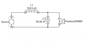
I've got a crossover that I don't quite understand. I'm familiar with simple 1st and 2nd order filters, but this one has what "looks-like" a Zobel, but the RC values appear all wrong for impedance purposes.
Hoping some one with speaker savvy can tell me what it's for?
It's the lo-pass section for a 6.5" mid-woofer in a 2-way system. Manufacturer doesn't provide driver specs, but the VC measures 3.2 ohms.

The 0.15 mH coil gives a nice 4520 Hz 1st order rolloff, quite appropriate for the system, but what in the world does the 60uF/1ohm RC bridge do?
1 ohm seems way too small for impedance use (@4 ohm driver), and 60 uF is way to big for 2nd order rolloff.
So I can't figure out what it is or does. Anyone?
Hoping some one with speaker savvy can tell me what it's for?
It's the lo-pass section for a 6.5" mid-woofer in a 2-way system. Manufacturer doesn't provide driver specs, but the VC measures 3.2 ohms.
The 0.15 mH coil gives a nice 4520 Hz 1st order rolloff, quite appropriate for the system, but what in the world does the 60uF/1ohm RC bridge do?
1 ohm seems way too small for impedance use (@4 ohm driver), and 60 uF is way to big for 2nd order rolloff.
So I can't figure out what it is or does. Anyone?
The 1 ohm is more than likely there to damp the resonance between the cap and the coil. It can also be to adjust the phase somewhat to get better phase alignment between the woofer and tweeter 🙂
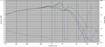
See attached sim. Black is without one ohm, blue is with one ohm.
Tony.
See attached sim. Black is without one ohm, blue is with one ohm.
Tony.
Attachments
Tony, thanks for the quick reply!
I'm more confused now though. Your circuit & plot don't look at all like I would expect (given your component values: 60uF & 150uH).
I don't have any hi-end modeling software, just use some calculators I found on the net, but none of them ever produce those approx. values for any crossover greater than 250-400 Hz.
I looked up the Peerless specs on the web (8 ohms nominal, 5.9 Re?), and using those, in order to get to 60uF cap, the crossover F3 is all the way down at 250 Hz, and even then calling for 2.08mH (2080uH?) coil, not 0.15mH.
And I'm not sure how to interpret your graph. What F3 is your calculation producing for that Peerless?
Or are you saying that 60uF + 1ohm is perfectly appropriate for a 2nd order F3 at 4.5 kHz using a .15mH coil?
What software are you using?
Sean
Crossover calculators are rarely correct due to their oversimplified nature. There is insufficient information. If they were to work properly you'd expect the response of the un-crossed speaker to be flat, and the impedance of the speaker to be simple and resistive (ie flat). Because of the typically non-flat impedance, the filter components will not work quite as expected, and due to the non-flat response, the wanted target for the filter isn't going to be as simple as what these filters would give anyway.
I understand all that. I'm not trying to build a crossover, or looking for absolute accuracy or precision.Crossover calculators are rarely correct due to their oversimplified nature...
I'm simply trying to understand what that RC pair does in the context of the crossover & driver that I have in-hand.
Regarding online calculators, I know they're not the be-all end-all, but so far they serve my purposes quite well.
When I put in the approximately correct parameters for the drivers I have in-hand (both tweeter & mid-woofer) and the approximately correct values for the design crossover point, they produce L & C values nearly the same as on the actual crossover! From there I can tweak the actual component values to exactly what is on the actual crossover, and get the individual drivers F3 points, and it all seems to be what is claimed for this speaker system.
So I'm happy with that. But it doesn't answer my curiosity, so the question remains.
Is the lo-pass circuit I posted above a 1st order at @4.5Khz with some sort of phase/resonance compensation as Tony surmised?
or is it a 2nd order, at what approx. frequency?
or something in-between?
Thanks!
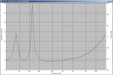
Hi seanc, maybe it will help if I show the impedance plot of that woofer.
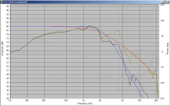
Note that I simply found a random woofer I had done a sim on before and plugged in the crossover values you gave to see whether any peaking occurred without the 1 ohm resistor (it did). It was only meant to show what effect the resistor has in the circuit (ie it damps the resonance between the coil and the cap). I've re-done the SPL plot with the driver inverted so the effect on phase is easily seen as well (and bigger, as I'm at work now and not using the laptop screen).
Without any impedance flattening on the woofer, the impedance at the crossover point is much higher and hence the effect of the components may not have been what you would expect.
The software I used for the demo was speaker workshop, which is generally very accurate, and will closely match real world results provided the frd and zma files used are accurate.
Tony.
Attachments

on the question about what it is, it would be a damped 2nd order electrical network. What it is acoustically will depend on the properties of the original woofer the circuit was designed for. It could be anything from 2nd order through 4th order acoustic in all likelyhood 🙂
Tony.
Tony.
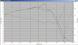
As an example, here is the same filter with an SB accoustics 4" midrange (actual measurements of a speaker I have made. This driver has an extended frequency response, and in this case this filter produces roughly a 2nd order L/R acoustic response with crossover frequency around 2.4Khz. red curve is the 2nd order L/R target at 2.4Khz and 88db.
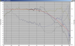
Third graph shows my MW144 woofers with the same network. Note how (raw driver lumpiness asside) they are already roughly 2nd order LR at 2.4Khz, and when the filter is applied they change to roughly 4th order L/R at 2.4Khz (blue).
Tony.
Third graph shows my MW144 woofers with the same network. Note how (raw driver lumpiness asside) they are already roughly 2nd order LR at 2.4Khz, and when the filter is applied they change to roughly 4th order L/R at 2.4Khz (blue).
Tony.
Attachments
Is the lo-pass circuit I posted above a 1st order at @4.5Khz with some sort of phase/resonance compensation as Tony surmised?
or is it a 2nd order, at what approx. frequency?
or something in-between?
Thanks!
It is 2nd order electrical with a damping resistor. The cap and resistor is not a Zobel. Tony has done an excellent job of showing you what happens to the 2nd order xo with the addition of the resistor. But as Tony has alluded to, it is impossible to say exactly where your speaker's xo frequency is without the correct frequency and impedance files of the drivers - which we don't have.
Tony and jReave, thanks for your efforts to educate me!
So, given the lack of TS data for the driver, with only the measured Re 3.2 ohm (approx. 4 ohm nominal impedance) available, my lo-pass circuit is 2nd order at roughly 2.4kHz.
Until an unless I can find more comprehensive software to use, I'll live with that. But it does not seem to be a good blend with the hi-pass on this crossover, so I'll continue to wonder.
Let me ask it differently. Here is the total crossover:

What is your best guess as to woofer F3, tweeter F3, and combined Fc?
Does it seem reasonable?
Does a Zobel (used in the typical fashion where R = driver impedance and C is calculated from driver Le) automatically imply a 2nd order filter as well?
Sean
ps. Speaker Workshop appears defunct, and it's a Windows app. I'm a Mac user, and it seems there's nothing good available, but I'll keep looking.
So, given the lack of TS data for the driver, with only the measured Re 3.2 ohm (approx. 4 ohm nominal impedance) available, my lo-pass circuit is 2nd order at roughly 2.4kHz.
Until an unless I can find more comprehensive software to use, I'll live with that. But it does not seem to be a good blend with the hi-pass on this crossover, so I'll continue to wonder.
Let me ask it differently. Here is the total crossover:
What is your best guess as to woofer F3, tweeter F3, and combined Fc?
Does it seem reasonable?
Does a Zobel (used in the typical fashion where R = driver impedance and C is calculated from driver Le) automatically imply a 2nd order filter as well?
Sean
ps. Speaker Workshop appears defunct, and it's a Windows app. I'm a Mac user, and it seems there's nothing good available, but I'll keep looking.
Alas, for those running Macs, emulators seem to be about the best solution to the software issue. Sorry.
TBH, we can speculate all we want re the corner frequencies of the filters, but without having the FR & impedance responses, that's all it would be: speculation, and frankly your guess is as likely to be correct as anybody else's.
Ditto whether it seems reasonable -well, as a circuit it will 'work' inasmuch as there's nothing fundamentally wrong about it in topological terms, but otherwise -we're back to guessing. One thing that does strike me about the low pass -that's a heck of a large shunt cap associated with a very small series inductor. Much larger than I'm used to seeing, but it depends on the drivers (and probably the age thereof, as general design characteristics change over time -for e.g., polyprop. cone designs with a smooth response are currently out of fashion, for better or worse). Come to think of it, the size of that shunt cap might even be a reason the resistor is there -a 60uF shunt to ground can make some amplifiers rather unhappy. 😉
No, a Zobel does not automatically imply a 2nd order filter. A pure RC Zobel is just there to flatten the rising impedance as frequency increases, and doesn't directly affect the frequency response. It does have an indirect effect however, because if, for example, you just stuck a series L on the driver assuming the impedance at the target XO frequency, the effect of that inductor will progressively reduce at higher frequencies, or to put it another way, you will have a lot less of an HF rolloff than you think. By flattening the impedance, the effect of the inductor will remain consistent.
Yah, but then I'd have to buy a copy of windows, which isn't worth it just to explore this.Alas, for those running Macs, emulators seem to be about the best solution to the software issue
And that's precisely what brought me here. If I'd seen more typical values, say 4-5 ohms, 10-20 uF or so, I wouldn't have given it a second thought.... One thing that does strike me about the low pass -that's a heck of a large shunt cap associated with a very small series inductor.
Thank you Scott!
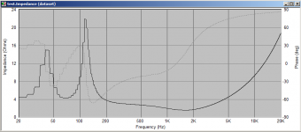
Yes, and I forgot to check what the impedance of that looked like!! It's bad. It may give the SPL target the designer wanted but it will certainly make a lot of amps unhappy!
See attached. Not sure what caused the lack of resolution at the low end in the impedance plot, as the original is fine. Never seen that happen before with speaker workshop.
It's dipping to about 1.5 ohms impedance with the data for my SB 4" driver.
Tony.
See attached. Not sure what caused the lack of resolution at the low end in the impedance plot, as the original is fine. Never seen that happen before with speaker workshop.
It's dipping to about 1.5 ohms impedance with the data for my SB 4" driver.
Tony.
Attachments
Yes, and I forgot to check what the impedance of that looked like!! It's bad..... dipping to about 1.5 ohms impedance with the data for my SB 4" driver.
Yah, and that's what my limited understanding thought it would do.
I'm not savvy with speakers in general, but my understanding of "impedance flattening Zobels" is that the resistor is chosen to be equal to, or slightly larger than, driver nominal impedance. And when the frequency rises to the level where the cap starts to pass signal, the resistor is effectively parallel to the driver, and so keeps the continuing impedance at or near the resistor value.
Seeing 1 ohm used on a 4 ohm driver & system didn't make sense to me, so I came here to ask.
Sean
Yes it is the combination of small coil and big cap that makes it an issue. You will see low value resistors in series with the shunt caps for the reasons I mentioned originally (and I suspect that logic was applied here) but from an impedance pov it doesn't work in this case.
Sorry I should have checked that at the start 🙂
Tony.
Sorry I should have checked that at the start 🙂
Tony.
Last edited:
No apologies needed Tony! I appreciate your patience and advice. I've learned something new!
I'll just have to assume the manufacturer did it right. Lacking all pertinent driver parameters, that's all we can do.
Thanks!
I'll just have to assume the manufacturer did it right. Lacking all pertinent driver parameters, that's all we can do.
Thanks!
- Status
- Not open for further replies.
- Home
- Loudspeakers
- Multi-Way
- Odd crossover, Zobel or Not?