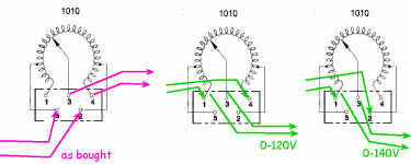
I just bought a Staco type 1010 autotransformer at an estate sale. the previous owner had put it in his own case but the way he configured it is not what is shown in the manual.
the 6 page manual is: https://www.stacoenergy.com/images/...nd-test-sets/stacovt/user-manual/003-1003.pdf
he has wired 2/5 as input and 3/4 as output (diagram is on page 2 of the manual)
when I test the output the range is around 6 to 180 volts.
is there a safety reason that I should rewire it to 1/4 and 1/3 as in the manual ?
did he do this configuration intentionally to get significantly increased voltage ?
While it is an autotransformer, you really should mention that it is variable. Variac is a particular brand, though technicians tend to call all brands of variable transformers "variacs." Yours is a Staco, but that is really the same thing as a Variac.
Hard to say why he did it, but to me, the plain old vanilla standard way is preferred, just for practical reasons. My bench variacs are wired for 0-140v output. I can dial it to 120v, but for testing I have the extra 20 volts available. If nothing else if the 120v from the wall sags, I can make up for it.
Hard to say why he did it, but to me, the plain old vanilla standard way is preferred, just for practical reasons. My bench variacs are wired for 0-140v output. I can dial it to 120v, but for testing I have the extra 20 volts available. If nothing else if the 120v from the wall sags, I can make up for it.
I've learned that it is a waste to ponder "why" the previous owners did what they did.did he do this configuration intentionally
Sometimes they had a good (to them?) reason. Sometimes they were befuddled.
Just put it back "right". 0-120V is good for "bringing up" gear to normal voltage. 0-140 would have been good when my workshop had a long-term power-cut and I only had 108V at my bench. Many things (all computers) worked fine, but power amplifier measurements came out way low. The upper end of the range would have been 126V, so I could apply 117V or 120V my choice.

Also strange is that with the "as bought" wiring, max output voltage occurs with full counter-clockwise rotation. This also seems unwise with respect to "muscle memory" habit. 😉