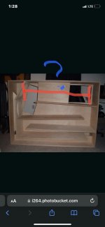
but it goes straight to 3:1 in a parallel 6th order ? Or the ‘overlap‘ is severely outta pressure phase/group delay/funky hiccup/etc ? (I removed 20 cm from the ‘one’ side ). 300/80cm instead of 300/100 in the scarred example
Attachments
Last edited:
Trying to avoid this situation as Scott Hinsons recent paper really aimed at this discontinuity issue.. wondering how much it applies/screws up the ‘OD MLTL’ Version ?
Optimum offset depends on box geometry. Given your stepped Olson/Nagaoka sytle taper you would have to model it. Most common option is placement to entirely or mostly kill the first unwanted harmonic.
dave
dave

Hmm, in a BP6P (AKA TH) you're still wanting the driver/vent to be at an odd harmonic, so at the very ends or offset with half of the distance at each end and for a DTS variant, off sets are based on its effective upper mass corner.
Actually, my quick 'knee jerk' response from memory failed me yet again. 🙁
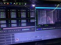
In a BP6P (AKA TH) you're still wanting the driver/vent to be at an odd harmonic, so at the very ends or offset with half of the distance at each end based on its effective upper mass corner (Fhm). The DTS is a 1/4 WL offset.
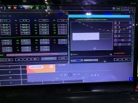
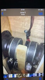
Sorry, no longer have a scanner or modern (camera) phone and never got around to learning any drafting programs, so best I can do is post a HR sim for you to reverse engineer. Fhm = 2*Fs/Qts = ~172 Hz
In a BP6P (AKA TH) you're still wanting the driver/vent to be at an odd harmonic, so at the very ends or offset with half of the distance at each end based on its effective upper mass corner (Fhm). The DTS is a 1/4 WL offset.
Sorry, no longer have a scanner or modern (camera) phone and never got around to learning any drafting programs, so best I can do is post a HR sim for you to reverse engineer. Fhm = 2*Fs/Qts = ~172 Hz
Attachments
Thankfully we both speak Horn resp! 👍🏼💚 Love it GM!
Attachments
Last edited by a moderator:
Assuming wall to wall, yes, i.e. '1' (fundamental) is an odd number/harmonic. 😉
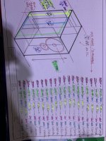
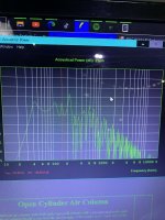
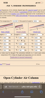
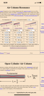
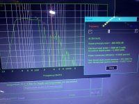
Resonant frequencies of air columns
Resonant frequencies of air columns
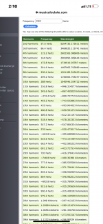
Ignore the ‘wavelengths’ on the long list of them Obviously .Odd harmoinic ?
Attachments
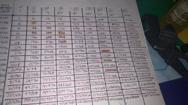
(12)7.2 full wave shapeOdd harmoinic ?
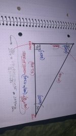
1/4 wave (90 degree part as p max/vmax) is 3(28.8)
/3 is 1(86.4)
/5 is 0.6(144)
/7 is .42857142… 201.6
/9 is
/11
/13….
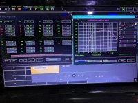
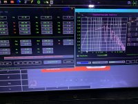
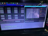
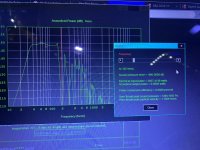
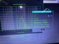
but look what shows up in horn response if you split this three to one exactly in ph1 mode
dead nuts…??
Attachments
Last edited:
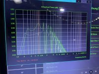
Yeah, the higher harmonics aren't affected nearly as much as the first few plus HR doesn't account for any box acoustic damping.
this slips away but I used the same 4” drivers as my mains to chase it pretty far in a rigid box before it all blurs…. Extremely intersting. Sequence on a 75 degree dayYeah, the higher harmonics aren't affected nearly as much as the first few plus HR doesn't account for any box acoustic damping.
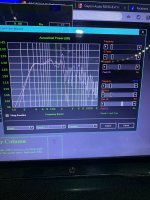
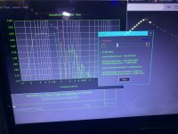
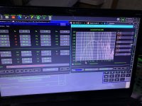
It seems the Real value comes in the fact that it is in fact 2 ‘perfectly aligned’ quarter wave resonators at 3:1 and offset at 3:1 (again) . It doesn’t have a big Scarr in the middle of the response that shows up in other things.??? I don’t understand why the typical base reflex only want to tune to 28.8, and then 57.6.? When if using quarter wave we go all the way to 144 from 86.4???this slips away but I used the same 4” drivers as my mains to chase it pretty far in a rigid box before it all blurs…. Extremely intersting. Sequence on a 75 degree day
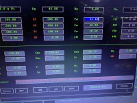
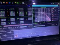
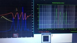
or as shown in this sim and measured impedance below
Attachments

Last edited:
- Home
- Loudspeakers
- Multi-Way
- OD ML-TL entry point