TI's own data shows it to have poorer LF voltage noise than the Philips part.
I got the TI parts as those were the only ones in stock at digikey/mouser, and I needed to order other things anyway.
I can offer you some pcb adapters I designed, just pay for the shipping, PM me if interested. You can order your own parts and solder them up. I'll even throw in some of the fine no-clean solder I use since buying a roll is a life times supply in my case. If you want me to solder & supply the parts then you are into more $ since I do not usually do this for others.
Cheers
Rick
Thank you however I would need everything ready to go. Maybe somebody else here wants to take that on and send me the finished items.
Here are results with the following added:
Since many people requested the NE5532, I have that particular result highlighted. This is still with a 100k load.
- Texas Instruments NE5532
- New Japan Radio NJM2732
- Analog Device LT1169
Since many people requested the NE5532, I have that particular result highlighted. This is still with a 100k load.
Attachments
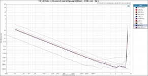

The color marking is not reliably detectable. You need to think about an other way to present the data I think.
//
//
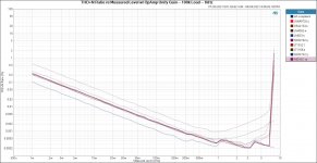

Cool, that's as I'd expect for the 5532. Yes, those colours are indistinguishable, a triumph of style over common sense I fear. Needs a combination of line style variation and saturated colours I think to make it possible to read the graphs. Pastel shades are not fit for purpose!
There seems to be a close agreement on noise floor with these devices, they all bunch together at low signal level.
To separate out some of the ultra-low-distortion opamps you'll need to do the noise-gain trick: https://www.ti.com/lit/ds/sbos450c/sbos450c.pdf (see section 8.3 on distortion measurement)
Cool stuff
Very little difference so far.
Would also be interesting to compare to some of the expensive discrete opamps .....
Very little difference so far.
Would also be interesting to compare to some of the expensive discrete opamps .....
I agree but who's going to pay? And really I'd like to see proper datasheets for many of these, some I've investigated seem to lack anything even approaching a decent datasheet so you are currently buying a pig-in-a-poke on many fronts (for instance voltage and current noise and 1/f knee). There are a few with better data, but its patchy.Would also be interesting to compare to some of the expensive discrete opamps .....
You have to be wary of the super high bias currents some of these devices have, I've seen 190µA quoted for instance - microamps, not nanoamps, note! That's going to severely restrict the values of resistors in the external circuit to keep bias IR voltages from saturating the circuit. And of course the current noise will a big issue as 190µA represents around 8pA/√Hz.
Of the discrete's I've looked at the Sparkos SS3601/2 seem to look the most promising, with 140dB of OL gain and low input current and low voltage noise quoted. Even the single amp version is $40 though - you can get a bunch of AD797's for that dosh!
"....current noise will a big issue as 190µA represents around 8pA/√Hz."
How does one figure that exactly?
How does one figure that exactly?
If you assume the input device generates shot noise, current noise density = sqrt(2qI)
where q is the charge on the electron, I is the current.
So:
sqrt (2 x 1.6e-19 x 190e-6) = 7.8e-12 A/√Hz
Its only a rough and ready approximation as how well the input device models as a source of shot noise depends
on various things - you really should measure it!
is unknown - basically any situation where charges have to jump a potential barrier can generate shot noise,
though when a current can flow unimpeded the electric field between charges can smooth out these fluctuations
(typically happens in metallic conductors which are usually modelled as shot-noise-free).
Shot noise - Wikipedia
Last edited:
Cool, that's as I'd expect for the 5532. Yes, those colours are indistinguishable, a triumph of style over common sense I fear. Needs a combination of line style variation and saturated colours I think to make it possible to read the graphs. Pastel shades are not fit for purpose!
There seems to be a close agreement on noise floor with these devices, they all bunch together at low signal level.
To separate out some of the ultra-low-distortion opamps you'll need to do the noise-gain trick: https://www.ti.com/lit/ds/sbos450c/sbos450c.pdf (see section 8.3 on distortion measurement)
Yes, agree, it seems it's really measuring the noise, with no distortion peeping out unless you get to several volts level.
Except a few that DO show distortion earlier but I have the same problem of not being to see which those are.
Jan
...I've seen 190µA quoted for instance - microamps, not nanoamps, note!...
Do you even believe that??

Without trickery, it suggests >20 milliAmps in the input transistors.
If there are any other funny numbers, I'd suspect ignorant marketing folks.
- Home
- Source & Line
- Analog Line Level
- Objective Guide to Op-Amp Rolling - Part 1