Hello everyone,
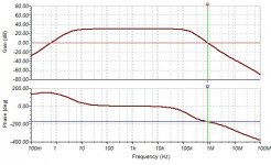
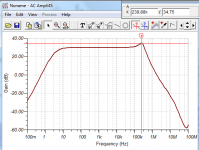
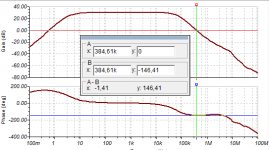
I'm designing a solid state power amplifier, and I'm adjusting the dominant pole capacitor at the VA stage. The problem is the phase shift that is near 180 degrees (175 degrees actually) at the output with 0dB voltage gain, could the amplifier meet the Barkhausen criterion and start self sustaining oscillations?
What I've to do to prevent this from happen?
Bode diagram attached,
Best regards,
Daniel Almeida
Attachments
Last edited:
Reducing Qvbe bias resistor value
Hello everyone,
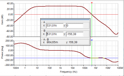
I've reduced the Qvbe bias resistor values and the phase shift is now between 150º and 160º at 0 dB (I think that those are acceptable values).
If I use a small capacitor between 30 and 50 pF, I've some kind of voltage gain "peak", I've simulated the progress of the output voltage at that frequency, and I've got a distorted signal but no positive feedback or oscillation.
When I use capacitors between 300-500 pF I've got terrible THD+N characteristics at 20kHz, and the 1kHz THD+N characteristics gets worse but the peaks disappear, why is this happening?
What's the best option?
Thank you very much for your concern,
Best regards,
Daniel Almeida
Hello everyone,
I've reduced the Qvbe bias resistor values and the phase shift is now between 150º and 160º at 0 dB (I think that those are acceptable values).
If I use a small capacitor between 30 and 50 pF, I've some kind of voltage gain "peak", I've simulated the progress of the output voltage at that frequency, and I've got a distorted signal but no positive feedback or oscillation.
When I use capacitors between 300-500 pF I've got terrible THD+N characteristics at 20kHz, and the 1kHz THD+N characteristics gets worse but the peaks disappear, why is this happening?
What's the best option?
Thank you very much for your concern,
Best regards,
Daniel Almeida
Attachments
Hello everyone,
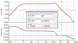
I've made this graphic using LM4702C (with the circuit similar to the one found in app note snaa045) to drive IRFP240/IRFP9240 and the result is similar, a gain "peak" is present, maybe the problem are the output devices?
Or TINA TI simulator?
Thank you very much for your attention,
Best regards,
Daniel Almeida
Attachments
Maybe a .TRAN analysis would give you additional insight into the circuit behavior?
If version_1 of the amplifier has gain-peaking in the AC analysis, but version_2 of the amplifier has no peaking, perhaps it would be revealing to simulate driving each of these amplifiers with a 1 volt peak-to-peak ideal square wave input (-0.5V to +0.5V), then look at the .TRANsient output.
If version_1 of the amplifier has gain-peaking in the AC analysis, but version_2 of the amplifier has no peaking, perhaps it would be revealing to simulate driving each of these amplifiers with a 1 volt peak-to-peak ideal square wave input (-0.5V to +0.5V), then look at the .TRANsient output.
Thank you very much for your fast reply
I've simulated both with sines at the frequency of the highest peaks and the wave becames distorted but with the same amplitude.
Maybe the problem could be the output pairs used?
PS: LM4702C TI amplifier also has gain "peaking", and I think that's strage.
In audio range the amplifier is linear and the sine waves are almost pure.
Best Regards,
Daniel Almeida
Last edited:
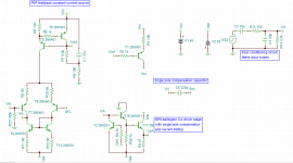
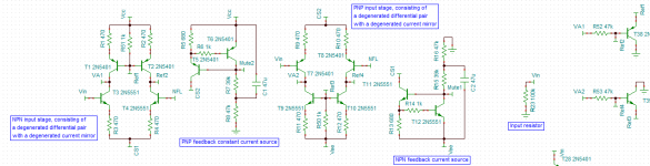
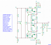
Hello evreryone,
Attached is the schematic of the circuit I'm testing.
This is a mirror image amplifier, with push-pull VA stage (current limited) and cascode loading, the constant current sources of the differential amplifiers are feedback current sources, the amplifier as two single pole compensation capacitors, the output stage consists of a vbe multiplier for output devices biasing, and also as short circuit protection and against inductive loads (with clamping zener diodes), the MOSFETs have gate stopper resistors to prevent high frequency oscillations, I've a resistor from sink to ground to reduce 2nd harmonic. The output stage consist of two vertical MOSFETs IRFP240 N-channel and IRFP9240 P-channel, the amplifier has a gain of aprox. 30 V/V for AC and 1 V/V for DC, the input is AC coupled, this amplifier also includes a Boucherot Cell (Zobel Network) to filter high frequency oscillations.
Thank you very much for your help,
Best regards,
Daniel Almeida
Attachments


Hi Daniel
This architecture looks attractive but has problems.
They have been discussed extensively - search for "Heeeelllppp"
The schematic in little pieces does not help, or at least it doesn't help me.
It is a creative way to achieve modularity but perhaps it would be easier for others if you presented your circuit more conventionally.
Best wishes
David
Last edited:
The current in your VAS stages will be pretty well indeterminate, or limited by your current limit circuits in the cascode path, neither of which you really want to happen.
You have two dueling high gain points, and even if you've made the simulator happy, real life won't be very kind.
Perhaps as an experiment, you could replace one of the VAS's by a constant current source...I know this won't preserve the mirror image characteristics, but as it is, I don't think it will behave well.
Once that's sorted out, the next issue is that the typical simulator mosfet models are awfully crude, and typically not very trustworthy. Perhaps yours are better than most.
Hello and thank you very much for your fast reply,
This schematic is made using TINA TI.
This architecture has problems? Where?
I'm sorry for making this questions, but that's my first design.
I've made the design in different pieces to avoid crossed connections and to distinguish the different blocks.
Best regards,
Daniel Almeida
This schematic is made using TINA TI.
This architecture has problems? Where?
I'm sorry for making this questions, but that's my first design.
I've made the design in different pieces to avoid crossed connections and to distinguish the different blocks.
Best regards,
Daniel Almeida
The design is maybe too ambitious for a first try, overcomplicated.
Design and build something simpler.
Design and build something simpler.
Hello and thank you very much for your help,
You are saying that a mirror image amplifier is impossible to build?
This topology I'm using is in great part from an electronics book, maybe I should throw my book to trash 😛
I've another design more simple with only one differential stage, but I really wanted to make a mirror image amplifier, but if it's not possible...
Best regards,
Daniel Almeida
Mirror image stage is quite possible. It looks like this one you have seen is from Randy Slone's book. While a pretty reasonable book, there were some mistakes in it...at least the edition I had...Sadly, Randy has passed away, and is no longer able to correct or comment. This amp with dueling high gain stages is one of those mistakes.
The Marshall Leach amps had the mirror image inputs, but didn't have two competing very high gain points. As such, the VAS stages had a stable operating point.
There are some simplifications you could do that would preserve the mirror image, yet get a stable operating point...the problem is, it's kind of hard to explain from far away...
Another design with darligton Va stage
Hello everyone,
Yes, you're right it's from Randy Slone's book.
I think you're right, so decided to do something more simple.
Attached to this file is a topology with darlington Va stage and a constant current source, the differential stage as a feedback constant current source, the output stage is the same with the protection system.
The short circuit protection works?
In simulations it works, but mirror image also works in simulations but not in reality.
Best regards,
Daniel Almeida
Attachments
Last edited:
The simulator is only as good as the models, and sometimes, the models will let it tell you some lies. It's not a lie that there will probably be some stable point found...it is a lie that the stable point would be repeatable in real amps.
But...the big question is...with the simpler amp...how is your distortion? How is your stability?
But...the big question is...with the simpler amp...how is your distortion? How is your stability?
This schematic is made using TINA TI.
This architecture has problems? Where?
I'm sorry for making this questions, but that's my first design.
I've made the design in different pieces to avoid crossed connections and to distinguish the different blocks.
Best regards,
Daniel Almeida
I somewhat edited my reply when I realized that the unusual layout was not due to the software but just your personal preference. I was too slow and you had already replied but better to read the more perceptive version!
If you are still interested then the problems are documented in many threads, just search in this forum for "Heeeelllppp" or "VAS and Slone".
Best wishes
David
Hello once more,
With the simpler amp the distortion is greater, specially at 20 kHz.
I've also found problems with stability because phase shift almost reaches 175 degrees.
THD at 20kHz is well over 1%???
THD at 1kHz aprox 0,01 %
Well I have to think about quit this project.
I don't have ideas of how to do a good audio power amplifier, all I've learned from that book is wrong.
I've to use analog audio driver ICs like LM4702 or LME48*** instead of discrete designs.
The probabillity of making a discrete amp that works is very low I think.
The problem is that I wanted to know how to make discrete designs but I think I don't understand the basics.
Best regards,
Daniel Almeida
Last edited:
Danny,
I know that it can be discouraging...It's probably worth another look after some time to relax.
I'd recommend Douglas Self's books on Audio Power Amplifier design. I think if you follow along with his designs, you will learn pretty well, may be able to get a better result.
It's also possible that your distortion results are more lies from the simulator. For example, if you don't force a small enough time step, the simulator will report distortion that isn't there. As a sanity check, you could check the distortion of your sine wave source when your output reports 1% distortion.
The source should always have all harmonics around 200 dB below the fundamental if the time stepping is ok.
There are also settling issues with the FFT, and windowing issues...any of these things being wrong can give misleading results.
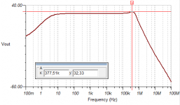
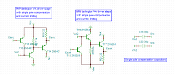
Mirror image amplifier solved?
Hello everyone,
I've seen this circuit in Bob Cordell's book and it's a mirror image amplifier, with improved current mirrors, as va stage I used a push pull va topology without current loading, the va darlington drivers are current limited.
Schematics an Bode diagram attached.
THD+N < 0,01% @ 1kHz
THD+N <0,5 @ 20kHz
Pout > 60 Wrms
Thank you very much for your attention,
Best regards,
Daniel Almeida
Attachments
- Status
- Not open for further replies.
- Home
- Amplifiers
- Solid State
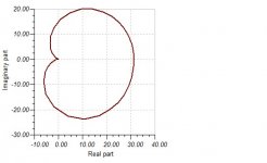
- Nyquist stability