Hi there,
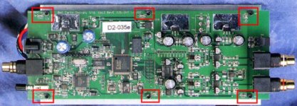
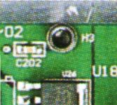
Yes, caps again 😛 I came upon a review of BelCanto's DAC2 in a french magazine. There's a nice photo of the mainboard (I'll scan it ASAP), and something puzzles me... The board is bolted on a metal plate, which acts as a shield, and separates the mainboard from the power supply and transformers (photo here), and I suppose it is connected to chassis ground. There are six screws on the mainboard, seemingly electrically connected to the bottom plate with threated mounting posts, and according to the photo on the magazine, each bolt's head seems to be connected to the PCB ground though a small SMD cap (sorry, I couldn't find a decent photograp showing these caps). And I wonder what is the exact purpose of those caps 😕 With my limited knowledge, I was assuming that chassis and digital ground connection had to be made at a single point, with plain and big wire...
I made a few searches on the web, and I couldn't manage to find something relevant (yes, H.H., even on www.sigcon.com), but perhaps I missearched 🙁
Any help/hints/link welcome...
exact purpose of those caps
I hate to go out on a limb here without seeing the circuit up close but I will take a shot. I believe the shield is to keep RF noise out of the analog circuits. The caps would couple the sheild to the analog ground plane. It may not be desirable to let analog signal or power supply currents flow through this shield so the caps provide an increasingly high impedence as the frequencies go down from RF to audio frequencies. This allows current flow at RF frequencies but inhibits it at audio frequencies. Being that the raw supply is right below the analog circuit, one also has to consider coupling of power supply noise into the analog circuits as well. Add EMI radiation from digital noise coupling to the power supply and you yet another consideration. Anyone still thing grouding is straight forward? There have been books written on the subject and the exact approach taken depends on many variables. Think this is bad you should look at the grounding for several racks of telecom equipment with the added concern of transient current of hundreds of amps from lightning.
http://www.amazon.com/exec/obidos/ASIN/0471245186/ref=pd_bxgy_text_1/104-5272109-0907141
http://www.amazon.com/exec/obidos/t...f=lib_dp_TFCV/104-5272109-0907141#reader-link
http://www.amazon.com/exec/obidos/ASIN/0750672706/ref=pd_sxp_elt_l1/104-5272109-0907141
http://www.amazon.com/exec/obidos/A...739/sr=5-2/ref=cm_lm_asin/104-5272109-0907141
H.H.
P.S.
Everything you wanted to know about heatsinks but were afraid to ask*
* well maybe were not afraid to ask over and over on this forum!
http://www.amazon.com/exec/obidos/ASIN/0791800741/ref=pd_sxp_elt_l1/104-5272109-0907141
Harry, thanks for replying and for references... and I didn't mean that grounding was straightforward 🙁
I also thought that it has something to do with analog vs digital ground, but the capacitors/bolts duets are also present at the bolts located near the analog section... where a high impedance device (ferrite beads) should have been more efficient to cut down RF noise coming from the shielding/grounding plate... But as usual, I talk without knowing 🙁
In the meantime, I found a post by Goudreau that says the same kind of things, but I keep on searching...
Sorry about that, I'll scan it tomorrow. I've tried to explain the setup the best I can, but I surely have missed some points.I hate to go out on a limb here without seeing the circuit up close
I also thought that it has something to do with analog vs digital ground, but the capacitors/bolts duets are also present at the bolts located near the analog section... where a high impedance device (ferrite beads) should have been more efficient to cut down RF noise coming from the shielding/grounding plate... But as usual, I talk without knowing 🙁
In the meantime, I found a post by Goudreau that says the same kind of things, but I keep on searching...
There is a grounding scheme presented on sigcon that seems similar; a large metal sheet connected to chassis ground (presenting extremely low impedance) is bonded to the PCB at many points. This was a brute-force approach to ground contamination in mixed-signal boards. It wasn't really recommended, but was presented as a potential solution for non-ideal setups.
If you aren't familiar with this I can dig the link up at lunchtime.
If you aren't familiar with this I can dig the link up at lunchtime.
Hi Tiroth,
Yes, would be fine to have the link, since my browser (Netscape 4.7x/Linux) doesn't feel comfortable with the new Sigcon's site layout (weird tables 🙁)
Thanks,
Yes, would be fine to have the link, since my browser (Netscape 4.7x/Linux) doesn't feel comfortable with the new Sigcon's site layout (weird tables 🙁)
Thanks,
Ground references
I used to work with Pete and he is an RF Guru. You should see some of the papers on digital decoupling he has written. Unfortunately they are proprietary to Alcatel. Check out your local technical bookstore for some on the references. I have read most of them and they are very good.
H.H.
I used to work with Pete and he is an RF Guru. You should see some of the papers on digital decoupling he has written. Unfortunately they are proprietary to Alcatel. Check out your local technical bookstore for some on the references. I have read most of them and they are very good.
H.H.
Here you go:
http://www.sigcon.com/Pubs/edn/multipleadc.htm
At least everything is in one place now (?) I think...
I never understood why there were two sets of articles that weren't cross-referenced.
http://www.sigcon.com/Pubs/edn/multipleadc.htm
At least everything is in one place now (?) I think...
I never understood why there were two sets of articles that weren't cross-referenced.
I guess I'll verbalize what everyone is thinking, that this cap approach is a supposed improvement of the sigcon scheme. I say "supposed" only because although it seems like a good idea (use the chassis only at RF) but it often seems that in EMC suppositions aren't good for much.
We could hope that they measured it both ways and this tested better...
We could hope that they measured it both ways and this tested better...
use the chassis only at RF
The sheild is not actually the chassis. After reading 4 books and a dozen artlcle on EMC, I found a spectrum analalyzer, an X-acto knife, and some copper tape were still useful tools in my quest to reduces EMI and noise in the circuit on my last project. Simulation and theory are no substitute for good test equpiment but are a great supplement!
H.H.
Sorry for the inexact language Harry. I was somewhat using the terminology of the sigcon article, which I guess does not correspond exactly with the board in question. Didn't mean to create any confusion.
- Status
- Not open for further replies.
- Home
- Source & Line
- Digital Source
- Nuts and bolts, and ground and ...caps