The meat:
With recent advancements in opamp accuracy, is it possible to construct a sensitive DC null meter?.....down to 1 microvolt ?
The details:
I have several commercial Null Meters (null detectors) from Fluke, HP, and JRL.
All of these but one (Fluke 887), use mechanical choppers.
Can a modern version be built, DIY ?
Now I will assume that to achieve the sensitivity of say, a Fluke 845,....that controlling noise, EMF, and signal guarding is half the battle...maybe more. It seems to be an art to attain stability at the microvolt level on the Fluke, or any of my other meters.
Am I making any sense?....or wasting my time?
=RR=
This is almost trivially easy today. Use battery power and one of the chopper stabilized opamps from LT. Way back I had a design for such published in Electronics Now as one part of a metrology series- voltage reference, null detector and KVD. What you get when you buy a Fluke 845 is mostly the wide range divider, 300V to 1uV or something like that. The LF noise performance isn't all that great. The HP419s are also nice, though the neon choppers are getting a bit long in tooth. Both units have trouble with their rechargeable batteries at this point, and the batteries are actually used as voltage regulators, so they have to be right for the units to perform well.
Did you use an analog meter (needle)?
So what is the basic circuit look like ?
(pardon my naivete)
For example, I have two voltages I want to match.
One is near 10volts DC (the unknown), the other is a 10v standard (the reference).
Is it something like ....one signal is passed through an inverted opamp, and the other through a non-inverted.......and the "unknown" is adjusted until they achieve a "null" at the two opamp's outputs?
If the answer is yes, is gain used in the opamps ?
I have some (highest grade) chopper opamps that are waiting for your answer (ha).
LTC1049 cn
LTC1052 cn
TLC2652 ai
TLC2654 ai
=RR=

Take the simplest case, comparing two ten volt sources. Ground 'em together, then hook your DVM between the two hot terminals. No ground connection to the meter. Read the difference. Now, let's assume you can adjust one of them, or that they're very close together. You need more gain so you can see 1uV or so. You'd use your battery powered stabilized opamp as a front end for your DVM. You could also just include a meter, but DVMs are common as dirt, so that's what I used. An interesting thing happens when the voltages matched. Whatever the impedance of the circuit is, high or low, the voltage across it is near zero. Thus, no current flows. It's because of this you can also do exact scale factors and measurements using a KVD or other divider.
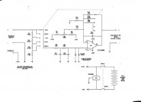
I have to see if I can find an electronic copy of the circuit I used. With my luck its probably on a 3.5" disk that I have no way to read anymore. I do have a paper one I can scan, but obviously that's less desirable. I used an LT1050, but several others are fine. It was a non-inverting amp, with a divider on the input ganged with a divider on the feedback. A DVM was used for the meter, set to 0.1VDC full scale. The most sensitive range was 10uV full scale input, giving insane resolution with any reasonable DVM. Watch out for the limited supply voltages on the CMOS opamps- I used a 9V battery and split it with a TLE2426. I also have a PCB layout for it. Gimme a couple days to find this.
I have to see if I can find an electronic copy of the circuit I used. With my luck its probably on a 3.5" disk that I have no way to read anymore. I do have a paper one I can scan, but obviously that's less desirable. I used an LT1050, but several others are fine. It was a non-inverting amp, with a divider on the input ganged with a divider on the feedback. A DVM was used for the meter, set to 0.1VDC full scale. The most sensitive range was 10uV full scale input, giving insane resolution with any reasonable DVM. Watch out for the limited supply voltages on the CMOS opamps- I used a 9V battery and split it with a TLE2426. I also have a PCB layout for it. Gimme a couple days to find this.
That's great.
Thanks for finding it.
The 100k trim is for....cal?
Would implementing a "guard" be worthwhile?
If so, it would be driven by....?? and start from...???
Actually something like this could be built in a small box with pins mounted (protruding), so it slides right onto the DMM's input jacks.....like a parasite.
=RR=
The trim for for residual DC offset. Even though the opamp is chopper stabilized, you're bound to have some slight offsets at the lowest scales. If I remember right, these opamps have enough trouble driving their own feedback, much less any load, so if you add an analog meter, add a second stage to drive it. No problem with a DVM. I made mine in a small metal box- the box is the shield and guard as I haven't seen any need for double enclosing it. It connects to the DVM with a few inches of cable and banana plugs, but you could certainly make it plug in directly.
The other parts of the original article were for a stable ten volt reference, but LT stopped making the metal package reference it was based on. Plastic packages don't have the long term stability of metal. There was also a scheme for doing a nice cheap KVD without expensive rotary switches. It simply soldered the resistors to the bottom of large pin headers, then you connected to the next bank with a plug on a pigtail. It was easily good to 10 PPM with careful matching of ordinary 1/4W MF resistors. With the voltage reference, KVD and null meter, one had the basics for a "Mini-Metrology Lab", the title of the series.
The other parts of the original article were for a stable ten volt reference, but LT stopped making the metal package reference it was based on. Plastic packages don't have the long term stability of metal. There was also a scheme for doing a nice cheap KVD without expensive rotary switches. It simply soldered the resistors to the bottom of large pin headers, then you connected to the next bank with a plug on a pigtail. It was easily good to 10 PPM with careful matching of ordinary 1/4W MF resistors. With the voltage reference, KVD and null meter, one had the basics for a "Mini-Metrology Lab", the title of the series.
http://www.edn.com/article/CA74477.html
is this the one?
But, I can't open the diagrams nor load Part 1.
is this the one?
But, I can't open the diagrams nor load Part 1.
Wrong author(s), but great info.
I think that was also published here...
http://www.linear.com/pc/downloadDocument.do?navId=H0,C1,C1155,D4177
=RR=
I think that was also published here...
http://www.linear.com/pc/downloadDocument.do?navId=H0,C1,C1155,D4177
=RR=
Yes, wherever I go, Jim Williams always seems to have gotten there first. I actually sent my manuscript to him, and he kindly proofed it for me. Only later did I get the latest LT data book at the time, and realized he had already covered most of what I did several years earlier. My article was written at the most basic level. I suspect Poptronix still owns the copyright, but I doubt it will ever see the light of day again.
If you want to "maintain the volt" the best way is with three ten volt references. You can intercompare them to 1uV or so, and when you send one out for cert, you can confirm that nothing changed before or after. I never have mine adjusted, only measured. That way I have history on drift. With three good standards and some history you can go many years between certs. Though everybody thinks they need yearly measurements, I can easily stay within a few PPM for five years or so. I used to keep history for my references and some standard cells in a program called Javilin. It was a spreadsheet aimed at time series, but it's long obsolete. Excel is ok too. You have to get in a habit of waking up, going down to the lab, and doing an intercompare at least once a week. For the reference in the article, I did this once a day for several *years* to confirm the design had long term stability!
If you want to "maintain the volt" the best way is with three ten volt references. You can intercompare them to 1uV or so, and when you send one out for cert, you can confirm that nothing changed before or after. I never have mine adjusted, only measured. That way I have history on drift. With three good standards and some history you can go many years between certs. Though everybody thinks they need yearly measurements, I can easily stay within a few PPM for five years or so. I used to keep history for my references and some standard cells in a program called Javilin. It was a spreadsheet aimed at time series, but it's long obsolete. Excel is ok too. You have to get in a habit of waking up, going down to the lab, and doing an intercompare at least once a week. For the reference in the article, I did this once a day for several *years* to confirm the design had long term stability!
Remember, I'm a hobbyist. To send a voltage source or resistor to NIST could be $1k or more. There are a few other places with Josephson Junction standards like Fluke and probably Keithley. Anybody with those standards will be way better than a part per million. I believe inter-comparisons between those standards have been done at part per billion levels! I just use a local calibration lab who probably uses one of the newer Fluke calibrators. Those would be sent to Fluke on a regular basis. As a (well calibrated) hobbyist, I only send out one of my voltage standards, and one L&N resistor. I think it cost under $200 for the pair, and I only do it every few years. From that, I can maintain the volt with two additional voltage standards. I have several resistor standards, but the one I send out is probably 50 years old, and has done all the drifting it's apt to do. Again, inter-comparisons detect any problems during the time between certs. With a good KVD, anything else I need can be derived with great accuracy from my V and R standards. Frequency is taken care of with a TRF receiver locked to WWVB. I have several GR inductance standards that are way overkill for most purposes. To keep the cap bridge (GR1615) in order, I have several friends with similar interests who pass around a GR 1000pF standard. Though it doesn't have a current cert, I'm pretty confident it's still within 5 ppm or less. OTOH, if I get my audio measurements within a percent, I'm perfectly happy 😀
Built it...
Hey Craig....
I built a quick version of your circuit.
Resistors are pretty well matched. I'll build a better version at some point (without a socket on the opamp, and better resistors and switch).
Pics....
http://i5.photobucket.com/albums/y177/Midiot/DSCN3508.jpg
http://i5.photobucket.com/albums/y177/Midiot/DSCN3509.jpg
You can see the backside of the switch, which extends through to the face.
I used some 5v regulators and two 9v batteries, until the rail-splitter part arrives.
I built it so that the two input BNC's shield is connected to case, but not to the circuit.
The inner coax wires of the 2 input signals....
.....one goes to your circuit's +IN
.....the other goes to ground IN
(all grounds are connected to one point, "star")
....the output coax, shield is at "star" ground, inner wire to output point.
(The output BNC is isolated from case.)
---------------------------------
Two questions.......
What is the best method for trimming offset ?
and...
The output is not entirely stable....even with no inputs connected, it will fluctuate a bit....example....at the 100mV setting it will hop around +0.05mV to 0.1mV (as read on my battery powered Fluke DMM w/coax cable). Is this the best to be expected ?
I tried to match my 1v references (diy, LM399a based) that have a "fine trim"......but it seems the trim is not fine enough !!
If working properly, your circuit has got some resolution !!
On my HP 3457a DMM, I can verify each 1V reference is at 1.00000v....
...but at the finer settings on your circuit, I see there is plenty of room for finer tuning that will not show on the HP meter.
I did switch the 2 coax cables into your circuit to check, and there is some offset, but hopefully, I can trim that out.
Thanks !
=RR=
Hi Redrabbit- don't know about Craig's circuit, but if you built mine, lock your DVM on the 100mV scale. The highest gain setting on the null meter will then be 10uV, plenty of gain and resolution for any known purpose. If you increase the gain of the DVM, you'll see noise, which is pretty much unavoidable. I kept a reasonable (for the application) bandwidth on the circuit, but you get into the trade-off of noise and bandwidth. Not sure about the opamp you used- could be faster than mine. The Fluke 845 and HP null meters are just as noisy as this one!
Back when I did the voltage reference that was part of the article, noise was the big problem. It's hard to remove random LF noise, and the best standard of comparison I found was the good old fashioned Weston standard cells. They can beat almost every solid state reference on LF noise. I seem to remember the saturated cells were better than the unsaturated. I can't afford one, but the high end LT reference chip might come close. I usually build zener references with the current set by the output of the buffer amp- self stabilized. With the right zener (selected for low noise) and the right opamp, they can be almost as good as anything, and you can fool with the zener current to get near zero TC. The rated zero TC current is ok, but never spot on.
BTW, what matters to me is long term stability, not short term LF noise. You need to inter-compare three references for weeks or years to really see what's happening, though for good audio references that probably isn't too important 🙂
I trim by shorting the null meter with a short piece of copper wire. On wire- find untinned copper wire. I pull it from old multi-conductor plenum phone wire. Tinned wire will have a high thermal emf against the terminals. If you just twist together some tinned and untinned wire, and attach it to the null meter, shorting it out, you can get big readings just by touching the twisted joint and heating it up. Watch for drafts and let everything stabilize if you're getting into the 1 PPM area. I find 5 PPM is easily managed, but 1 PPM gets annoying because of all the thermal and noise problems.
Sorry Conrad, I know a Craig (Hoffman), and mentally typed that name by mistake...
=Randy Leifer=
(RR)
=Randy Leifer=
(RR)
Conrad Hoffman said:Remember, I'm a hobbyist. To send a voltage source or resistor to NIST could be $1k or more. There are a few other places with Josephson Junction standards like Fluke and probably Keithley. Anybody with those standards will be way better than a part per million. I believe inter-comparisons between those standards have been done at part per billion levels! I just use a local calibration lab who probably uses one of the newer Fluke calibrators. Those would be sent to Fluke on a regular basis. As a (well calibrated) hobbyist, I only send out one of my voltage standards, and one L&N resistor. I think it cost under $200 for the pair, and I only do it every few years. From that, I can maintain the volt with two additional voltage standards. I have several resistor standards, but the one I send out is probably 50 years old, and has done all the drifting it's apt to do. Again, inter-comparisons detect any problems during the time between certs. With a good KVD, anything else I need can be derived with great accuracy from my V and R standards. Frequency is taken care of with a TRF receiver locked to WWVB. I have several GR inductance standards that are way overkill for most purposes. To keep the cap bridge (GR1615) in order, I have several friends with similar interests who pass around a GR 1000pF standard. Though it doesn't have a current cert, I'm pretty confident it's still within 5 ppm or less. OTOH, if I get my audio measurements within a percent, I'm perfectly happy 😀
i was just curious. i was a Calibrator in the Army. it's fine that you have standards that work and cross checks between them is a very good way of maintaining them, as long as there are no systemic errors (such as all of them drifting in the same direction at the same rate due to temperature or aging) but the more you cross check between, the smaller the possibility of such a systemic error happening without some indication that something is amiss. our lab at Ft Campbell was a secondary transfer lab, and so we didn't maintain any primary standards. our secondary standards were on a regular schedule for calibration at the Army's primary lab. our secondary standard for voltage was an HP voltage standard which was a digitally programmed voltage source. our frequency standard was a WWVB receiver with a synchronized crystal oven. our responsbility was to maintain the calibration of all test equipment on Ft Campbell. it would get interesting when we had to calibrate something when we weren't allowed to know what it was for....
Would something like this be worth investing in? http://www.gellerlabs.com/standards.html They charge $10 to re-calibrate the voltage standard. Seems inexpensive, but I do not know enough to decide if the product in worthwhile in the first place.
http://www.gellerlabs.com/standards.html
Conrad Hoffman said:Remember, I'm a hobbyist. To send a voltage source or resistor to NIST could be $1k or more. There are a few other places with Josephson Junction standards like Fluke and probably Keithley. Anybody with those standards will be way better than a part per million. I believe inter-comparisons between those standards have been done at part per billion levels! I just use a local calibration lab who probably uses one of the newer Fluke calibrators. Those would be sent to Fluke on a regular basis. As a (well calibrated) hobbyist, I only send out one of my voltage standards, and one L&N resistor. I think it cost under $200 for the pair, and I only do it every few years. From that, I can maintain the volt with two additional voltage standards.
http://www.gellerlabs.com/standards.html
- Status
- Not open for further replies.
- Home
- Amplifiers
- Solid State
- Null Meter...build one?