May I suggest editing the OP and stating what the fix was? Saves people from reading the entire post to find out it was oscillation.
Not sure what OP is.May I suggest editing the OP and stating what the fix was? Saves people from reading the entire post to find out it was oscillation.
Disconnected the NFB and problem solved. When I installed new tubes 6 months ago I inserted a 680pf + 10K in parrallell to the 47K in the feedback to get a little more sparkel to the treble. Remove this and now its working as it should. Shocking.
I don't know why you find it shocking, you modified a feedback circuit.
You need to find a scope if you can to troubleshoot these issues a lot quicker. There's plenty of videos that will guide you thru troubleshooting with a scope. I gave you a list of things to check first and told you it was oscillating. Screwing around with a feedback circuit is a quick way to get an amp to oscillate. I would suggest using variable devices to dial in feedback so you can dial it back.
Oscillation can be one of the most difficult problems to troubleshoot, even seasoned engineers can have a difficult time tracing but it can be isolated by shorting (if possible) different stages of the amp. Sometimes it can be just a bad ground connection, a dirty tube connection or a leaky cap. You left out the most important part of troubleshooting, you never revealed that the amp had been modified. Modified amplifiers are the most difficult to troubleshoot!
The answer was in my first post--
Check the 100K resistors
Check the -62v bias bias voltage
Check the value of cathode resistor
Check the plate voltage (check for AC component)
"If all good, its either a tube or the OPT or the amp is oscillating (check with a scope)"

What are the odds on an amplifier working with changed NFB arrangement for 6 months without problems, only to than start to oscillate in both channels? And what are the odds on an amplifier doing this both on its normal spot, as well as lying opened up on a working bench, likely with different secondary loads connected to it (resistors instead of loudspeakers, or atleast different loudspeakers)?
How does one get 529 Vdc from 380 Vac with just one diode, so with half-wave rectification?
And if the amplifier is a normal stereo amplifier in which the two channels share the HV supply, how than is it possible that all the voltages except the cathode voltages of the KT88's measured according to the schematic while the tubes of one channel were taken out?
Note: I didn't yet know post #35 when I posted #36.
Last edited:
Apparently the odds are good, components drift over time, it was close enough for the circuit to oscillate.
Look at the entire circuit, the power supply is connected to the part that is oscillating which is like a voltage amplifier. Think of it like a switching power supply.
The cathode just sets the current for the tube, think of it as a diode blocking or isolating the rest of the circuit to ground.
Look at the entire circuit, the power supply is connected to the part that is oscillating which is like a voltage amplifier. Think of it like a switching power supply.
The cathode just sets the current for the tube, think of it as a diode blocking or isolating the rest of the circuit to ground.
Wich 'entire circuit'? The power supply in the schematic in post #1 can't deliver the stated 529 Vdc to begin with. It's also still unclear if the two channels share one power supply or not.
Last edited:
If you can't identify this amp shares a power supply, you probably should have some else do the troubleshooting.
It would clearly have another power transformer
It would clearly have another power transformer
And now you react with something that is supposed to be an ad hominem...but which is actually flawed.
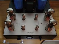
Attached is the only picture of the amplifier in this thread. How can you deduce from it without a doubt that the two channels share one power supply? I can't. I think I can see three pieces of iron on the picture. But even when the two channels do share one PT, there still must be more than three pieces of iron since the minimum is 2 x OPT, 1 x PT and 1 x choke. And if there really is only one PT, how can you deduct from this picture that this one PT doesn't have seperate windings for the two channels? I already know the anwer on this one: You can't.
That's why I asked TS about it but the only answer I got is that it is "a normal stereo amp" (see post #13), which to me didn't clearify things.
What I can deduce from the picture is that the power supply very likely is different than the schematic in post #1. The picture shows four adjustable resistors, two per channel. If the two adjustable resistors for bias level would share the same voltage source, adjusting one of them for lower bias would lower the bias of the other channel too, which ofcourse would be absurd.
And what about the 529 Vdc from 380 Vac with half-wave rectification? If you are a competent troubleshooter, you surely must be able to shine some light on this...
Attachments
Last edited:
None of my posts in this thread even remotely point into the direction that I own the same amp as TS.
My guess is that you wrongly thought that I was TS, else I would really not know how you could come to your assumption.
My guess is that you wrongly thought that I was TS, else I would really not know how you could come to your assumption.
Last edited:
- Home
- Amplifiers
- Tubes / Valves
- Now I`m really confused.