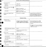
I see this page in the manual of my scope (which is still in transit, I only have my 10x probes at the moment) tektronix 2213. Does this mean I can connect a maximum 800V of AC into the scope's inputs with no probe attenuation?
I've heard a few warnings about hooking the scope up to house power from a wall outlet. If you can measure 800V peak to peak of AC with this scope, why couldn't you connect the hot and ground of house power up to this scope? If so, why would you ever need to attenuate with the 10x scope probes?
The whole manual is here: http://www.hellspark.com/dm/ebench/tools/Analog_Oscilliscope/tektronix_2213_service.pdf
Attachments
One (probably the main) advantage of using a 10x probe is that it makes the impedance of the scope 10 times that of using a direct connection to the scope's input. This won't matter for most measurements, but for high impedance circuits such as the grid of a vacuum tube, 1 meg is a substantial load and will change the measured voltage, and 10 meg impedance of a 10x probe will give a more accurate reading.
I use my scope for testing new amplifiers.
The first test is for DC fault on output.
I connect scope to output and power up the amplifier and check to make sure there is zero volts on the output. If the voltage is to a rail I power off and find the fault.
If it is close to zero I trim the DC adjust pot to get zero volts.
The next test is setting up the bias pot.
I apply a sine wave and monitor the output on the scope.
To start with there will be crossover distortion.
I slowly turn up the bias until the crossover distortion goes.
Job done.
x1 probes are quite slow and round off square waves, attenuate spikes etc but will be usable for non critical audio. Typically, a x10 probe lets the scope work to its full bandwidth specification, cheap ones are rated to 150Mhz but this is with x10. Most ordinary probes are rated to 600v max.
I've used a huge HV probe to measure 22Kv with an ordinary scope and a DVM at work, I've no idea how much one of them costs!
I've used a huge HV probe to measure 22Kv with an ordinary scope and a DVM at work, I've no idea how much one of them costs!
- Status
- Not open for further replies.