Yes, Kay Pirinha, I installed all of those capacitors !17-15. I will have to replace the expensive multi-capacitor can with two separate capacitors. the "multi" caps that share a common connection wont work if one of them is reverse polarity. So, I wasted about $50 on that mistake.

I have all the capacitors replaced and I am now getting -69 volts from anode of diode to ground. That is a huge improvement!I would guess it's somewhere around -75VDC to -100VDC at the diode anode.
If the diode is original, I would replace it regardless, to avoid trouble.
Make sure capacitor polarity is correct.
Check the resistor value.
You also suggested that if I replace the old selenium diode with a modern silicon diode, that I should put a 1k ohm resistor in series. I have not done that. can you tell me how important that is?
Thanks
🙂
It seems now that won't be needed. So what's next, have you tried to bias the amp now?
If not, start with the most negative voltage first, (most amps have this as full counterclockwise) and gradually adjust.
If not, start with the most negative voltage first, (most amps have this as full counterclockwise) and gradually adjust.
Last edited:
I'd strongly recommend to replace any selenium component in any appliance, 'cause the question isn't if it fails, but when it fails instead. In your amplifier a series resistor isn't absolutely necessary with a modern silicon diode, but it won't hurt OTOH.
Best regards!
Best regards!
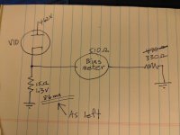
I replaced the selenium rectifier with a 20A10 silicon diode. I got both 20mF caps replaced with the correct polarity. All 4 output tube cathodes are now reading a very pleasing -50 vdc. The plate volts are 462 vdc. I used a biasing tube amplifier from https://www.amplifiedparts.com/tech-articles/tube-amplifier-bias-calculator using output tubes 6550 and a plate voltage of 462 vdc. The original meter to ground resistor was 470 ohm reference assembly book schematic, attached. The book said to change it to 330 ohms, so I did. Originally, it needed more current through the meter to get the needle on the bias line, but i'm not certain why they wanted it changed. maybe because instead of 117acv, i'm using 127acv out of the wall? bottom line is that with all output tubes warmed up, all cathode 15 ohm resistors to ground are 1.26vdc which calculates to .084 A and that is very close to the 90% bias point on that website I was using. I think the bias meter on the amplifier uses voltage to calculate current, so it isn't actually measuring amps in the cathode. If you change the meter resistor, you can get it to read anything you want lol. if you look at the drawing from the book and the one on yellow paper, you can see what i'm talking about. I still have to go through the balance procedure, but I wanted to finish getting my voltage measurments and tidy-up a bit before I put the cover back on and turn it over to it's normal upright position. It is as Rayma pointed out, capacitors were the problem.
Attachments


Good that the tubes are still ok.
Make sure that bias meter agrees with your lab DVM reading.
Make sure that bias meter agrees with your lab DVM reading.
Yes sir, I think they are all still good. While I was waiting for my capacitors to arrive, I started working on a B&K Dyna-Jet 707 as it needed a bunch of capacitors and resistors changed. I also replaced the tube socket as there was a lot of moisture damage/corrosion inside. After cleaning and getting stuff replaced, I was almost complete with the calibration and got hungry so left it on while I had a bowl of soup and while my back was turned, the transformer let all its smoke out. such a waste and so stinky. Now, I am looking for another one. I'd like to find another 707 so I will have spare parts.
As for the bias and dvm reading. The meter only takes 1.5 ma to deflect to the bias line and that may be how it is designed, but the actual ma current draw from the cathode is 84 ma and that is right where I need to be for the 42 watt dissipation. I bought one of those octal tube adapters with the two leads coming out and when I get this thing turned over, I can try using that to run current through the meter to check the bias. I'm pretty sure it will match the calculated value from the cathode resistor to ground. Thank you, Rayma. Your advice was of great value to me.
As for the bias and dvm reading. The meter only takes 1.5 ma to deflect to the bias line and that may be how it is designed, but the actual ma current draw from the cathode is 84 ma and that is right where I need to be for the 42 watt dissipation. I bought one of those octal tube adapters with the two leads coming out and when I get this thing turned over, I can try using that to run current through the meter to check the bias. I'm pretty sure it will match the calculated value from the cathode resistor to ground. Thank you, Rayma. Your advice was of great value to me.
Which power tube bias current did HK instruct for this amplifier? An plate dissipation of 42 watts at idle appears to be much on the high side, I think, unless it's instructed.
Anyway, you really don't have to mess with that 470 or 330 Ω resistor in series with that meter. Just set the DMM at the 2 Vdc range, measure the voltage drop across the cathode resistors, calculate: Ic = UR/15 and adjust bias accordingly.
Best regards!
Anyway, you really don't have to mess with that 470 or 330 Ω resistor in series with that meter. Just set the DMM at the 2 Vdc range, measure the voltage drop across the cathode resistors, calculate: Ic = UR/15 and adjust bias accordingly.
Best regards!
Yes, Kay Pirinha, I did as you say, measure cathode resistor voltage drop. First, I adjusted bias using meter on back of amp. then, I measured voltage drop across 15ohm cathode resister 1.3v to get 86ma (close enough for me). In the assembly manual, whenever it mentions the output tubes, they say Kt-88/6550. I didn't buy them as they were already installed when I purchased this unit.
Attachments
- Home
- Amplifiers
- Tubes / Valves
- novice rebuilding HK Citation II, at his wit's end