Hi,
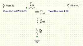
In order to remove a spike in my speakers around 2.7Khz I want to place a notch filter.
I have tried it with success in unbalanced configuration but so far have failed in balanced mode.
The notch filter is in the image attached.
For balanced configuration I thought I would duplicate the notch filter: One for the + and one for the -, but it did not work.
A friend told me that may be the IN should be the + and the Out the -. Sounds strange...
My equipments are purely balanced: I have Pass X0 and a Krell FBP450MCX and have no unbalance to balanced transformers..
Looking for ward advice, explanation how this is supposed to work.
Thanks.
Attachments
For balanced configuration I thought I would duplicate the notch filter:
One for the + and one for the -, but it did not work.
For the balanced version, use a series resistor (of half the 4.2k value) in both input lines,
taking the balanced outputs after the resistors. The three shunt RLC components between
the resistor outputs stay the same, and there are no grounds in the filter circuit.
You would have been successful in using an identical filter circuit in each balanced input line,
if the ground ends of the RLC networks were disconnected from ground, and instead
connected together. However, that would unnecessarily use 6 shunt components instead of 3.
The shunt R and L would be twice, and the shunt C half, the unbalanced values, so that the
notch frequency would remain the same.
Last edited:
That might do funny things to phase, unless the two filters really were identical. As it is the filters in each stereo channel need to be as similar as possible - assuming the two speakers are identical too!rayma said:You would have been successful in using an identical filter circuit in each balanced input line,
Thank you for this feedback.
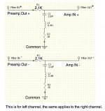
So if I understand correctly the drawing below is what I need to do for each channel?
No, see the post #2 above.
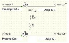
For either channel, connect as follows:
A series 2.1k in both the + and - phases of the channel.
The three (not 6) series RLC notch parts between the output ends of the 2.1k resistors.
The outputs from each 2.1k. No grounds anywhere.
More like this (unrelated) diagram, but with your RLC in place of the C1.
http://experimentalistsanonymous.com/diy/Schematics/Tone Control and EQs/Passive mic LP Filter.jpg
Last edited:
Balanced impedance connections require that BOTH sides of the balanced signalling see identical impedances.
It seems you had forgotten this.
It seems you had forgotten this.
To whom are you telling this?Balanced impedance connections require that BOTH sides of the balanced signalling see identical impedances.
It seems you had forgotten this.
The last schematic is absolutely fine wrt to impedance balancing, of course the series resistors have to be reasonably matched, however the output impedance of the pre will have an influence too.
But anyway, I'm not that much concerned about CMRR in home applications.
EDIT: Was a bit late, DF96 confirmed.
Balanced impedance connections in general have a very high impedance to common/ground/earth .
some approach 10M but 100k is more common for electronic style circuts.
Sticking in a 36r +11nF+0.4mH (shown in post4) connected to com/ground completely defeats the high impedance normally sought.
some approach 10M but 100k is more common for electronic style circuts.
Sticking in a 36r +11nF+0.4mH (shown in post4) connected to com/ground completely defeats the high impedance normally sought.
Agreed, but that is not what the balanced impedance connection aims for.
It tries to maximise the impedance to ground so that any ground influences are minimised.
Then the connection and particularly the Receiver just have to process the differential signal between the two poles of the balanced signal.
It tries to maximise the impedance to ground so that any ground influences are minimised.
Then the connection and particularly the Receiver just have to process the differential signal between the two poles of the balanced signal.
If the impedances to ground are equal, the ground influences should be anyway minimised, as it is a common mode influence per definition. Of course then mismatching will play it's role, as we use real components.
But anyway, I'd always go for the last solution presented.
Also for avolume control. But the amp topology has to "follow" in that case.
But anyway, I'd always go for the last solution presented.
Also for avolume control. But the amp topology has to "follow" in that case.
- Status
- Not open for further replies.
- Home
- Source & Line
- Analog Line Level
- Notch filter in balanced configuration between Amp and Pre Amp