Hello Inductor.
I tried 3rd order too, but it seemed best response the 4th order because the resonance at 5kHZ in the mid was in a lower SPL scale.
Right now I have 2 ways to follow:
1.- Buying Xover components, build, measure and then tweak....
or
2.- Measure each driver in the final speaker cabinets and then, with the FRD and ZMA files (phase included) try to design the Xover again.
I'd rather prefer to follow the second option because I will learn a lot... but I need to know how to make measurements of raw drivers in their final enclosure... any help?
As I told before, I have a Behringer ECM8000 mic (not calibrated) and an M-Audio fast-Track USB with phantom power card.
Thank you
I agree you should do option #2. You've got a lot of xover parts to order there so, you should be as accurate as possible with your modelling as not to end up tossing aside some of the parts. To do that , take the measurements with the drivers in the cabinets and input the new .frd and .zma files with phase info in PCD. You may be surprised how much different the xover may look.
With regard to taking good PCD measurements, you should visit PE techtalk forum and do a search or, contact Jeff Bagby directly.
One more question for all of you:
I'm about to buy a Behringer ECM8000 calibrated mic from iSEMcon laboratories (Germany) to do my speakers measurements.
iSEMcon.com - Welcome to iSEMcon
They offer me the standard calibration and a calibration plus consisting on the 90 degrees calibration data (diffuse field)
Do I need the calibration PLUS or just the standard one?
thank you again!
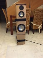
Here am I again with the speakers almost finished.
I took measures from every driver installed in the bafle and simulated a crosover... but I really don't know if thats the best solution.
Can anybody help me?
Attached you can find the measurements files and the designed crossover with Xsim free crossover designer:
http://libinst.com/Xsim/XSimSetup.exe
Can anybody help me to improve the crossover?
Thank you in advance
Attachments
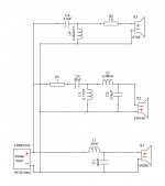
I really can't say if it'll sound any good, but see how the sim goes when you add a 0.2-1uF tank to the 0.48mH mid filter coil. Notch effective around 5 to 10kHz anyway. Usually straightens out phase a bit and lose some metal ringing. On a flat baffle, a third order tweeter usually works better too.
This sort of thing: boxsim-db.de | Boxsim Projektdatenbank
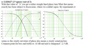
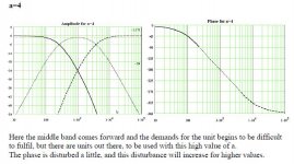
It usually helps to keep in mind where you are going on this with a target response. It's a Steen Duelund idea. Linkwitz-Riley, IIRC.
This sort of thing: boxsim-db.de | Boxsim Projektdatenbank
It usually helps to keep in mind where you are going on this with a target response. It's a Steen Duelund idea. Linkwitz-Riley, IIRC.
Attachments
Last edited:
- Status
- Not open for further replies.
- Home
- Loudspeakers
- Multi-Way
- Notch Filter Calculator