Notch Filter and Crossover Calculator
Hello everybody:
I'm plannig a new building: Vifa XT25 + Fountek Fw146 + Fountek Fw200
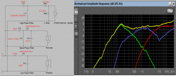
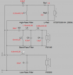
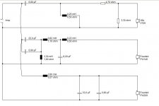
I have calculated a theoretical crossover from the FRD/ZMA cueves traced with SPL Trace from the manufacture's data. Attached you can find the Xover.
What I can't calculate not simulate is the appropiate Notch filter needed to smooth the resonance on the Fw146 at 5kHz.
Could anybody help me or calculate the appropiate notch filter?
I think the filter should correct from 5 to 20 kHz about 12db/octave
Thank you in advance to everybody!
Hello everybody:
I'm plannig a new building: Vifa XT25 + Fountek Fw146 + Fountek Fw200
I have calculated a theoretical crossover from the FRD/ZMA cueves traced with SPL Trace from the manufacture's data. Attached you can find the Xover.
What I can't calculate not simulate is the appropiate Notch filter needed to smooth the resonance on the Fw146 at 5kHz.
Could anybody help me or calculate the appropiate notch filter?
I think the filter should correct from 5 to 20 kHz about 12db/octave
Thank you in advance to everybody!
Attachments
Last edited:
Not a great idea to attenuate the response of the bass driver.
Better use more sensitive midrange and pad it later. You are
making yourself job more difficult working with aluminum.
Try increasing the C and L value for the mid LP filter and see
how it looks. If that does not help, add another inductor for a
3rd order. After these modifications you will know better how
to proceed.
I suggest the OP download Xsim software (free) and try his design once again as a sanity check. Harris Tech., while nice, is not my favorite any more since the recent release of Xsim by Bill Waslo. There is a thread in this forum from BW that introduces the software.
Well, trhe problem, as a newbie, is that I have bought all the stuff and built the cabinets... so I have to work with those drivers and find the way to make them work.
If somebody wants to help me, I can sshare the X-Over 3 filer, Xsim file, FRD and ZMA files....
Thank you again.
If somebody wants to help me, I can sshare the X-Over 3 filer, Xsim file, FRD and ZMA files....
Thank you again.
It would be nice posting the FRD and ZMA files as .txt @diyAudio.
You need to change the termination (only the termination name as txt file to post here) to do that.
You need to change the termination (only the termination name as txt file to post here) to do that.
At the same time post the size and volume of the speaker you envisioned, like the front baffle dimensions and depth, internal volume in liters and type of alignment (frequency for a BR)
The cabinets volumes where calculated with Bassbox6.
Fountek FW200 needs about 23l CLOSED box.
Bass section is 700h x 170w x 200d all milimeters what means 23,8 liters.
Will be very very heavy damped.
I attach the FRD and ZMA files from all the drivers and the front baffle.
Sizes in milimeters.
the Zip files are RAR files in fact, but I had to rename it to be able to be uploaded.
All the stuff is at home unless Xover components since I'm getting crazy to design it.
Thank you everybody for your help.
Attachments
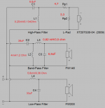
raelman,
with the same values I got different results than what you posted.
This is just for the sake of a principle in general and not a solution
per se. I simulated in PCD7 by Jeff Bagby with parts as shown in
the schematic.
Since you have drivers and box already built, make the measurements
and then use frd and zma for simulation.
Attachments
Last edited:
Your sim seems to be good. I have triespd the same sheet from Jeff baggy too, but in any case it can't smooth the mid resonance at 5khz.
Any idea?
Thanks for your simulation.
Any idea?
Thanks for your simulation.
... but in any case it can't smooth the mid
resonance at 5khz. Any idea? Thanks for your simulation.
I tried to add a series RLC in parallel with the midrange driver and it
changed tweeter response a bit better but screwed up mid response.
I would not worry too much about it.
That bass response looks rather disapointing. I would consider a 1st order xfer function so the woofer response gets extended 100-200 hz out beyond its 150 hz peak before rolling off. I think it's optimistic to believe that system line between 150 and 1 kHz will be that flat. I suspect there will be more of a dip between those two frequencies once he gets to the point of taking some actual acoustic measurements.
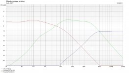
I have tested a 4th order in the LP section of the MID filter and this is the result.
Seems to be better than my first approx.
Do you think it's a good starting point to be built?
Thank you.
Yes, a good starting point. Breadboard the xover outside of the cabinet so you can easily change out parts for final tweaking. Do you have acoustic measurement gear? You'll need it in addition to your ears.
Yes, I have a Behringer ECM800 mic and M-Aidio Fast Track audio card to take measurements.
Thank you
Thank you
The problem is that the simulations are lacking the phase part of the Founteks frd/zmas for an accurate phase/output prediction. Phase is only present for the tweeter.
That would be nice to have measurements in the final baffle. 🙂
raelman,
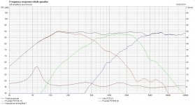
I did the same as you (following Lojzek post #9) as an experiment, but at this time with a 3.order on the Fountek crossing with the tweeter, what gave the mid driver more 7dB attenuation @6Khz. I see that you posted a 4.order for the mid in your latest post and changed resistors for the tweeter.
That would be nice to have measurements in the final baffle. 🙂
raelman,
I did the same as you (following Lojzek post #9) as an experiment, but at this time with a 3.order on the Fountek crossing with the tweeter, what gave the mid driver more 7dB attenuation @6Khz. I see that you posted a 4.order for the mid in your latest post and changed resistors for the tweeter.
Attachments

The problem is that the simulations are lacking the phase part of the Founteks frd/zmas for an accurate phase/output prediction. Phase is only present for the tweeter.
That would be nice to have measurements in the final baffle. 🙂
raelman,
I did the same as you (following Lojzek post #9) as an experiment, but at this time with a 3.order on the Fountek crossing with the tweeter, what gave the mid driver more 7dB attenuation @6Khz. I see that you posted a 4.order for the mid in your latest post and changed resistors for the tweeter.
What SW are you using for your modeling? It's looks quite complete.
Hello Inductor.
I tried 3rd order too, but it seemed best response the 4th order because the resonance at 5kHZ in the mid was in a lower SPL scale.
Right now I have 2 ways to follow:
1.- Buying Xover components, build, measure and then tweak....
or
2.- Measure each driver in the final speaker cabinets and then, with the FRD and ZMA files (phase included) try to design the Xover again.
I'd rather prefer to follow the second option because I will learn a lot... but I need to know how to make measurements of raw drivers in their final enclosure... any help?
As I told before, I have a Behringer ECM8000 mic (not calibrated) and an M-Audio fast-Track USB with phantom power card.
Thank you
- Status
- Not open for further replies.
- Home
- Loudspeakers
- Multi-Way
- Notch Filter Calculator