Thanks to Russ and Brian for the guidance and the PIC🙂
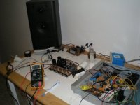
Today I got the preamp and headphone sections working. I have two question
1. Has anyone measured the dc output at max volume?
2. Brian any chance I can buy a few of those -95 to 0 and 95- to +24 PICs
Today I got the preamp and headphone sections working. I have two question
1. Has anyone measured the dc output at max volume?
2. Brian any chance I can buy a few of those -95 to 0 and 95- to +24 PICs
Attachments
digi01 said:i like your nice work.forward😉
zang
Thanks
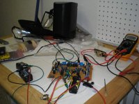
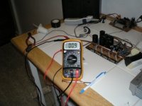
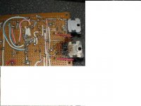
Doing alittle testing with a 7.5watt bulb in series with supply
Attachments
with +/-9volt ,I dare not go higher(no heatsinks and all). The offset is low with caps after the opa552.
The highs are crisp and clean,no hum some hiss at about a inch from tweeter. Vocal are clear. Im looking forward to the full supply test,hopefully sometime this weekend.
The highs are crisp and clean,no hum some hiss at about a inch from tweeter. Vocal are clear. Im looking forward to the full supply test,hopefully sometime this weekend.
Attachments
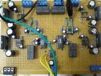
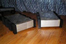
This is my selector. It has
4 RCA inputs
3 XLR inputs with bal to single converter
2 buffered tape loops
I plan to use 4 transformers
1 for left,1 for right and one for led plus relays. A addital transformer for the #2 tape loop.
Tested today,all work as it should
4 RCA inputs
3 XLR inputs with bal to single converter
2 buffered tape loops
I plan to use 4 transformers
1 for left,1 for right and one for led plus relays. A addital transformer for the #2 tape loop.
Tested today,all work as it should
Attachments

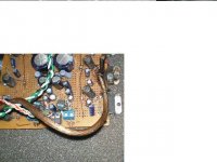
I need help with this one!
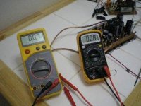
I getting voltage between speaker terminal and case. I measured between power supply including both rail and ground,no voltage and resistance is more than 20meg. The chips are isolated. The voltage start at about 1.5mv and increases as temp go up to 17volts.
The voltage at both terminal start at .05mv and increases to 25mv.
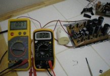
Decided to test the amps with a fuse instead of the lightbulb between the mains and powersupply. I had one chip go boom. Tested the same amp with chips gone works fine,I guess that where the high output voltage came from. Iam going to replace the chip and see what happens.
Attachments
- Status
- Not open for further replies.
- Home
- Amplifiers
- Chip Amps
- Not yet