I hope there is someone with greater understanding of this matter here.
Long story short. I am into classic cars and especially Volvo 1800. Those lack a third brake light and now I have seen too many rear ended, so I need to do something about it. Sure there is an easy way to find something that fits, but I rather go the long way and create something like it was designed with the car from the beginning.
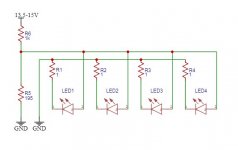
I am trying to figure out the wattage values for R5 and R6 and I don't like the values I come up with as those are some big resistors. I am trying to feed the array with 2.2 to 2.4V and from what I understand I can manipulate the resistance accordingly to obtain this.
The 3W LEDs have 2.1V forward voltage and 350mA forward current. R1-R4 are 1/8W 1 Ohm.
Thank you for any help I get.
Long story short. I am into classic cars and especially Volvo 1800. Those lack a third brake light and now I have seen too many rear ended, so I need to do something about it. Sure there is an easy way to find something that fits, but I rather go the long way and create something like it was designed with the car from the beginning.
I am trying to figure out the wattage values for R5 and R6 and I don't like the values I come up with as those are some big resistors. I am trying to feed the array with 2.2 to 2.4V and from what I understand I can manipulate the resistance accordingly to obtain this.
The 3W LEDs have 2.1V forward voltage and 350mA forward current. R1-R4 are 1/8W 1 Ohm.
Thank you for any help I get.
Attachments

That's like Christmas lights... one goes out - they all go out. I prefer parallel and not serial for this reason. Thank you tho.
Unless you're purchasing cheap no-name brand LED's, I've never seen series LED strings fail due to one "burning out".
To invest in good LED's, like Luxeon, Cree, etc, it's a one-time "do it and never worry about it" project, so long as the LED's are run at or under their rated volts/current.
Additionally, to insure reliability, a simple regulator/driver is wise to impliment.
To invest in good LED's, like Luxeon, Cree, etc, it's a one-time "do it and never worry about it" project, so long as the LED's are run at or under their rated volts/current.
Additionally, to insure reliability, a simple regulator/driver is wise to impliment.
The one I am planning on using is Cree. At 1.6mm x 1.6mm SMD it gives off 400lumens. I do not plan doing this over in near future so no no-name parts. Life is too short for such.
I met my partner in a 1800.
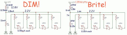
Yes, you are doing it wrong. You do NOT try to derive 2.2V from the car's uncertain electric system, then try to get current-sharing with a teeny resistor. The LED is whatever voltage it wants to be. YOU get as much excess votlage as you can muster, and use Ohm's Law to pick a resistor to pass the design current (0.35Amps in this case).
Your demo plan puts less than a milliAmp in each LED. Totally lame. Scaling for the desired 350 milliAmps, the total power consumption is as LOT for the 1800's mellow alternator (I recall we took parts off a Jensen P1800 with a generator??).
With about 8.8V needed from 11-15V, THE sensible thing is ONE series string. Ah, total failure. I drew two other more fail-safe plans. And the competition.
Attachments

Unlike filament lamps, LEDs rarely fail burnt-open. At the usual "life limit" the LED still conducts fine but the quantum wells are not making as much light as they did when new. Assuming for economy you had little reserve light at installation, when light output falls to 85% 70% 50% whatever the installation fails specs. However even 50% light is not much less to the logarithmic eye, and is a lot better than no light at all.
I grant that there's other burn-open failures in wires and mounting so a diversity plan may be wise.
I also note that a BRAKE LIGHT only runs when brakes are being used. While some folks use the pedal for a foot-rest, people who change their own brake pads don't. 10 hours STEADY braking might wear pads to the bone, so the million-mile 1800 may have 200 hours of braking and brake light. (To argue against this guess: 1966 Chevies never have all 6 tail-lamps working at once because they burn-out as fast as you can replace them.)
(Pads or shoes? Memory fades-- she's had the Miata a lot longer than the 1800.)
Attachments
Last edited:
There are plenty of 12V LED globes of variable power and form factor on Ebay and the like, just connect connect across existing brake lights circuit and you are done.I hope there is someone with greater understanding of this matter here.
Long story short. I am into classic cars and especially Volvo 1800. Those lack a third brake light and now I have seen too many rear ended, so I need to do something about it. Sure there is an easy way to find something that fits, but I rather go the long way and create something like it was designed with the car from the beginning.
I am trying to figure out the wattage values for R5 and R6 and I don't like the values I come up with as those are some big resistors. I am trying to feed the array with 2.2 to 2.4V and from what I understand I can manipulate the resistance accordingly to obtain this.
The 3W LEDs have 2.1V forward voltage and 350mA forward current. R1-R4 are 1/8W 1 Ohm.
Thank you for any help I get.
These LED globes contain internal current regulator stage so no futzing with big high power resistors is required.
Max.
I have designed a few commercial LED lamp modules for special applications. The difficult part is the thermal design. Be sure to have a good enough heat dissipation system. If you allow the LED chips to overheat, they will fail in a short time. Do not try to run the LEDs near the manufacturer design limits, unless you plan to bolt the circuit board on a huge heatsink. On special applications like yours, it may be more cost effective to use more LEDs at lower current. Aluminium PCB is not required for medium power LEDs such as the one you plan to use, but large copper tracks are. Use automotive rated parts if you want to maximise life. To drive the LEDs, you may use a special purpose PWM driver chips, it will not dissipate heat. Resistors are the next choice: use several of them in series, to spread the heat, and connect the LEDs in a series string. I suggest 2512 SMD power resistors, they are easy to solder and very though. This is an automotive application: it must survive jumpstarts and voltage spikes. Add a small value resistor in series to the positive terminal followed by a zener diode.
Probably 4 x 3W LEDs are way overkill for brake light. Combined brightness will exceed motorcycle headlight.
Yup, way too bright.Probably 4 x 3W LEDs are way overkill for brake light. Combined brightness will exceed motorcycle headlight.
Ebay - 12v led globe
Max.
The amount of light is set by several factors: shape, type and material of the plastic cover, angle of emission etc. 4 x 3W (at 50% current) may be a good starting point. By the way, the required minimum and maximum amount of light is specified on local regulations. Check this data or do a comparison with a commercial product, and adjust the LED current to match.
so long as the LED's are run at or under their rated volts/current.
It's a car with a battery as source. DC. There is no Vr.
> The difficult part is the thermal design. Be sure to have a good enough heat dissipation system. If you allow the LED chips to overheat, they will fail in a short time.
Yes but:
> Volvo 1800. Those lack a third brake light
Brake light on a well-driven car is not a long-term application.
> This is an automotive application: it must survive jumpstarts and voltage spikes. Add a small value resistor in series to the positive terminal followed by a zener diode.
The LED will resist momentary voltage spikes *exactly* the same way a Zener would. This just adds more parts to fail.
>> LED's are run at or under their rated volts/current.
> DC. There is no Vr.
Under ratings does not need a reference voltage. Long-term the poor dynamo can't maintain much over 14.4V or the battery will boil dry. There are 23V jumps and 100V dumps-- the 100V dump is a choke of limited energy and I bet Bear will not let a 24V jump near his beloved 1800. Anyway that is <double current and double power in LED. 4X power in resistor, but only a minute. And the brake light is probably NOT on for the jump?
> maximum amount of light is specified on local regulations
Yes indeed, and I generally object to these punks with over-bright mis-aimed hyper-blue headlights. However as a brake light on a low-slung vintage car, the police I know would stop it more to see the cool old car than to give the Warning. As a fellow driver, I'd only see it if following, and after the forst WOW stop I would give plenty of space between my nose and his tail. (Which is part of the idea.)
Since those older cars have primitive technology compared to modern vehicles, it's wise to consider overall voltage fluctuations of the alternator/system.
From 12, to perhaps 16 volts can be fed from such a system, depending on battery charge condition and equipment loads.
Thus, if using senitive illumination like LED's, which require some careful regulation for long reliable life, it's simple to build in regulation.
A constant-current regulator is the best bet.
That harsh, extremely hot/cold, vibrating environment calls for a special montage. Common PCB soldering technique can't be used. The LEDs have to be fixed independent from the soldering.
That harsh, extremely hot/cold, vibrating environment calls for a special montage. Common PCB soldering technique can't be used. The LEDs have to be fixed independent from the soldering.
I think that's being a bit paranoid, and overkill.
Thought I would chime in because I have some experience, at least I actually did put an incandescent third brake light in an old car, modified a side marker light to use as a third brake light on my utility trailer, and am currently modifying a tail light for my old dirt bike (i.e. whatever you are thinking, I probably have built something similar). Have to say I agree with the advice to just use auto LED bulbs and matching sockets for whatever custom light body you are building or modifying. You get a robust electrical and mechanical design all in one package, just about any form factor you want.
Last edited:
- Home
- Member Areas
- The Lounge
- Not audio related.