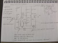
Just though I would share this circuit which I used in my TDA1543 nos dac. I removed the op amps and coupled the DAC into this buffer which uses a 6418 tube driving into a source follower to the output. The circuit uses a little feedback for greater stability and can drive very low impeadances down to 1K ohm without any increase in distortion. Although the response is flat up to 35Khz it seems to sound not as crisp and harsh on the highs and after listening for a while it is almost impossible to revert back to the op amp setup. The mids are highlighted and the highs are well presented but not over exagerated. I have only setup the gain at 2 but it has an open loop gain of only about 6.
It is a very affordable solution if you want to try a tube output on your DAC.
I invite anyone out there for your opinions about this. The DAC is a kit I got a while ago from HIFIDIY.net which runs 8 parralled TDA1543's.
Sorry for the poor schematic quality. I just quickly hand drew it.
Regards
Billy D...
Attachments
Last edited:
thanks billy, this might be just what i was looking for 😉
was this inspired by the oatley line stage by any chance?
was this inspired by the oatley line stage by any chance?
NOS dac tube buffer output
Oatley is just up the road from me (very convenient to get the tubes) and yes I used the k295 PCB and modified it.
The PCB is of very good quality and it withstood all the soldering and desoldering as I was testing different combinations. The other kits he has need more tweaking as there are certain design flaws which I have already spoke to them about. This is by far much better design with a higher supply voltage used and FET source follower output. Feed back put the icing on the cake and improved it even better. If you need open loop gain the feedback network can be omitted. It worked very well without it aswell.
Regards
Billy D...
and suppose i wanted to do without the trimpot on the input, what gain am i looking at? (5.5 i suppose? [i'm a total noob at this stuff which's why low voltage supply is such an welcoming thing])
Since it's NOS, are you planning to add the sin c correction? (~ + 4db @20k)
Parallel RLC in series with the IV resistor (47 ohms) creates a peak @ 20k

http://www.diyaudio.com/forums/tubes-valves/197920-thorstens-tube-stage-tda1541a.html
Sin C Envelope Correction:

FAQ: DDS Tutorial - SINC Envelope Correction | EngineerZone
Cheers,
Jeff
Parallel RLC in series with the IV resistor (47 ohms) creates a peak @ 20k
http://www.diyaudio.com/forums/tubes-valves/197920-thorstens-tube-stage-tda1541a.html
Sin C Envelope Correction:
FAQ: DDS Tutorial - SINC Envelope Correction | EngineerZone
Cheers,
Jeff
dac tube buffer
The cct is as simple as it gets. Low voltage and small in size comparison. A cheap way to experiment "tube sound". You can omit the trimpot and also the 100k ohm resistor if you want the preamp/buffer to to have the full gain. There is no problem with that. I included it in so I can reduce the output because there was too much drive. No I am not planning to put any post filtering at all. To raise the highs by 4 dB? All the ccts I have seen on the web have not implemented such a thing for the TDA1543 or the TDA1545. The highs don't seem to be lost but that "CD sound" with "rich" highs has been tamed down which has made them sound more clear and more natural and to me that is more pleasant to the ears.
Regards
Billy D...
*************
Last edited:
i also particularly don't need the roll-off compensation cuz my pi4 speakers start rolling off at 14k, but the circuit is thorsten's design so it has it's merits.
Nice
Hi billbo, Thanks for posting this. I happen to have a few of those tiny tubes in my parts bin. 🙂 Will have to try that out. I'm slow at times getting it done.
Hi billbo, Thanks for posting this. I happen to have a few of those tiny tubes in my parts bin. 🙂 Will have to try that out. I'm slow at times getting it done.
dac buffer
If you get around to make up this cct please send some feedback on this thread . I will be curious to read your opinions.
Regards
Billy D...
**************************************
If you get around to make up this cct please send some feedback on this thread . I will be curious to read your opinions.
Regards
Billy D...
**************************************
Circuit revised
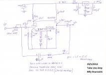
I was asked the question in regards to the biasing of the tube in the thread http://www.diyaudio.com/forums/analog-line-level/236628-simple-low-voltage-tube-preamp-stage.html which made me revisit the design of the cct.. In essence the bias takes the average voltage that is across the filament (approx 0.6 volts). In real tests it showed to be about 0.1 to 0.3 of a volt. I considered this is too low and would pose a problem driving the tube positive. This is not a real problem if you can drive high current from the source but it is not recommended for audio. I did more research and redesigned the cct. to have more grid bias. (about 1 volt). The revised cct. has a 100 Ohm resistor which will give 1 volt bias and raised the supply voltage to 30 volts. This has greatly reduced distortion and has made the cct. more stable.
Once again sorry for the hand draw schematic.
Regards
Billy D...
************************************
Attachments
Last edited:
Question
What diodes are used in the string in the filament section? I will have to look for that fet too. That is a new one for me. 😱
I was asked the question in regards to the biasing of the tube in the thread http://www.diyaudio.com/forums/analog-line-level/236628-simple-low-voltage-tube-preamp-stage.html which made me revisit the design of the cct.. In essence the bias takes the average voltage that is across the filament (approx 0.6 volts). In real tests it showed to be about 0.1 to 0.3 of a volt. I considered this is too low and would pose a problem driving the tube positive. This is not a real problem if you can drive high current from the source but it is not recommended for audio. I did more research and redesigned the cct. to have more grid bias. (about 1 volt). The revised cct. has a 100 Ohm resistor which will give 1 volt bias and raised the supply voltage to 30 volts. This has greatly reduced distortion and has made the cct. more stable.
Once again sorry for the hand draw schematic.
Regards
Billy D...
************************************
What diodes are used in the string in the filament section? I will have to look for that fet too. That is a new one for me. 😱
parts inventory
The diodes are basically there as a safeguard to protect the filaments. If anything happens to the supply voltage the diodes will conduct and clamp the voltage at around 2.4 volts which will not harm the tube filaments. any small rectifier diodes will do. I used the small signal diodes 1N4148. As far as the fet is concerned, you do not have to use the fet I used. Use a good fet which has a voltage handling of at least the supply voltage (30 volts) and handle at least around 20mA. I just happen to have these fets and that is why I used them. They are overkill for the job since they are a 250 volt 310mA device. Don't stress on these components. Just use what you have or can get.
Regards
Billy D...
***********************************
No I am not planning to put any post filtering at all.
Depending on what your amp is following the DAC you might well find improvement in implementing a passve anti-imaging filter. That's because the DAC's image frequencies increase IMD. Valve amps tend to have lower IMD so if you're using a SS amp I'd guess the improvement will be more marked - it certainly was in my case. My soundstage opened up enormously when I introduced such a filter.
I have some filter schematics up on my blog - click the number in the margin to the left of this post.
i also particularly don't need the roll-off compensation cuz my pi4 speakers start rolling off at 14k ...
I suppose that's one way of looking at it ... but another way is now you've got double the rolloff! It's even worse!!1!!
Thorsten said it and I'll repeat it: you have to fix the NOS sinc rolloff. Even if you're old, even if you don't have tweets, even if ....
If you don't, you're just listening to rolled off digital ... and haven't really heard NOS ...
And your 4Pi's don't roll off at 14k ...
Pi Speakers - four Pi loudspeaker performance data
PS You should get Wayne's new horn, he's perfected it sooo much it doesn't need the top-octave compensation anymore!!! 😀
Hi AudioLapDance,
can you tell me what values should I change according to the schematic in your post #5 so that I'll obtain the same +4dB gain at 20khz but with an 100 ohm resistor in the equation as the I/V (rather than with that 47 ohm posted there)? thanks
can you tell me what values should I change according to the schematic in your post #5 so that I'll obtain the same +4dB gain at 20khz but with an 100 ohm resistor in the equation as the I/V (rather than with that 47 ohm posted there)? thanks
For the sake of sinplicity, build the circuit and try it out. I have insralled it as is. To me it sounds better than my other dacs and thats what counts. At least I have a dac that sounds different so I have diversity. For the novice at heart it is a good project even as a preamp.. This is a DIY forum where beginners have subscribed and can appreciate simple modifications.
Last edited:
I suppose that's one way of looking at it ... but another way is now you've got double the rolloff! It's even worse!!1!!
Thorsten said it and I'll repeat it: you have to fix the NOS sinc rolloff. Even if you're old, even if you don't have tweets, even if ....
If you don't, you're just listening to rolled off digital ... and haven't really heard NOS ...
And your 4Pi's don't roll off at 14k ...
Pi Speakers - four Pi loudspeaker performance data
PS You should get Wayne's new horn, he's perfected it sooo much it doesn't need the top-octave compensation anymore!!! 😀
you're absolutely right. i had a bit of a head smack moment there. i still haven't finished the speakers yet so we'll see how much i want the compensation afterwards.
what horn are you talking about?
Hi AudioLapDance,
can you tell me what values should I change according to the schematic in your post #5 so that I'll obtain the same +4dB gain at 20khz but with an 100 ohm resistor in the equation as the I/V (rather than with that 47 ohm posted there)? thanks
Yikes, looks like I overstepped here billbo, sorry. 😱 Taking another look at our circuits ... they are very different. And I think I can help you out:
You mention your 4x1543 DAC but what wasn't included was the DAC output circuit. I'm guessing it's a regular IV resistor (guess 400 ohms) scaled (4x 1543 Iout) to get about 1-2Vrms output.
This voltage is then 'buffered' (and amplified a bit) by your tube circuit.
My circuit is more of an IV convertor rather just a buffer for voltage.
Sorry for the confusion. 😱
All O.K. mate. This is what the forum is all about. The DAC is actually 8xTDA1543's. I/V resitor is about 2.2k/8 = 275Ohms (I used 270 ohms) and the VRef resistor is 1.5k/8 = 187.5 ( I used 180 ohms). I will post some pics and more specs on the respose of the output.
Regards
Billy D...
Regards
Billy D...
Cheers, mate!
So, to add sin c compensation to your DAC you'd have to scale the peaking circuit (.15mH, 330nF, 27 ohm) to your IV resistor (270 ohm instead of T's 47 ohm)
Or you could include the compensation in a 2nd order filter with your x2 tube circuit. Instead of a proper smooth roll-off (q=.7), you create a peak @ 20k (q=1.0?) that adds a few dB to compensate the sin c roll-off! Elegant! (I think CarlosFM and T tried it ... there's a TINA op-amp circuit around somewhere ...)
But you'd have to 'nail-down' your circuit a bit more (no adj gain, etc...)
- Status
- Not open for further replies.
- Home
- Source & Line
- Digital Line Level
- NOS DAC with tube buffer output