Dear All,
I want to make a good NOS dac based on AD1865 fed by a CS8414. I do not know what PSU would be the best for it. I'm thinking about shunt regulators based on LM431s, mainly for the analog supply.
Do you have experience with different regulator/psu circuits ?
The filter at the output is temporary, a transformer will follow the DAC chip than a 6072 fed with a 6X4.
Thanks,
JG
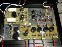
Attachments
Hi Giordano,
I looked at your schematic and having used related current dacs from AD they work better with 20mV or less of audio on their outputs to prevent linearity issues. (They are designed to drive the virtual earth represented by the input of the I/V converter circuit - which is a transimpedance amplifier.) That 270 ohm resistor should be more like 10 - 20 ohms, check the specification for the 1865 to see how much voltage can be tolerated on the outputs before performance starts to degrade.
Transformer coupling works well as long as the impedance reflected back to the dac current output is within an acceptable range.
Oddly enough many of the newer current dacs no longer specify this value, I guess the expectation is that everyone will use an I/V converter with an input that looks like a virtual earth.
I did not focus on the oputput yet, but thank You very much for the info about that.
What do you think about the power supplies ? (series resistor values not set yet)
Regards,
JG
What do you think about the power supplies ? (series resistor values not set yet)
Regards,
JG
kevinkr said:That 270 ohm resistor should be more like 10 - 20 ohms, check the specification for the 1865 to see how much voltage can be tolerated on the outputs before performance starts to degrade.
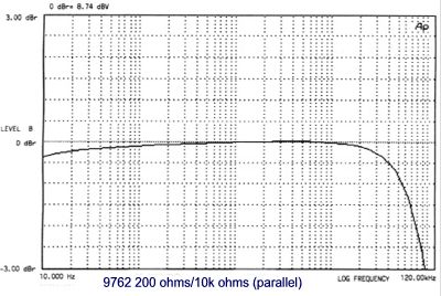
Kevin, my experience with the 1865 is that up to about 200R is good for the I/V. Sowter even recommends this value when using their I/V transformer: http://www.sowter.co.uk/specs/9762.htm
Things like the 1541, on the other hand, don't like higher than about 33R.
Hi Doug,
Have you actually measured distortion with various I/V resistor values to see whether or not there is a correlation between load resistance and distortion? I expect that measurements would probably indicate that lower resistance values are better in this regard. Since this thing is a mix of r2r ladders on the low order bits and binary weighted current sources on the high bits (segmented dac) there may well be an issue or not, I'd be curious to know either way.. Sorry to be such a pain.. 😉
http://www.analog.com/en/prod/0,2877,AD1865,00.html
No measurements, but it is NOS, so I'm not sure how much good they would do. I'll try to do some in the near future, though to see what it looks like. I believe AudioNote uses ~122R or so (actually, the schematic I've seen has a 380, a 221, and a 1K all in parallel.)

One more important question I would have :
On all the drawing I have seen so far, the "analog" supply of the 8414 is supplied from the digital supply, but the analog ground of the 8414 with the filter is connected to the analog ground.
Is this normal ?
I do not feel good about it, since it makes current from the digital psu through the anlog ground, analog-digital connection and than digital ground (or the way back with the phisical current flow).
A less important thing, I see a suggested reset circuit in the datasheet of the 8414, but nowhere implemented, as well as some D/A converter requires that at powerup, the analog supply comes up first, this is not guaranteed anywhere either - in the other hand I thrust it is not necessary. The first thing makes me more nervous.
Please let me know how you do and why.
Thanks,
JG
One more thing :
How do you switch between digital sources. I need 3 input, minimum 2, a toslink and a coax.
I plan to use an Omron G6K to switch both lines and use the differential input of the 8414. I think AND gates should be better, but than I can not use the differention input of the 8414 and I have to make a differential receiver for the coax. G6K is a small signal relay, it was giving acceptable performace at a volume control, the best I have tried so far, but on base band signal.
It is in the 10MHz range, so I'm not sure it is good any more.
So, what would you use ? Small sigla relay is good ?
Thanks,
JG
Attachments
Hi Giordano,
Search for "SDS Audio Labs CS Crystal CS4329 DAC". This pdf article will give you clear understanding on how to implement the grounding topology.
dsavitsk is showing on his website the properly implemented SPDIF input circuitry. He's picked-up the best input isolation transformer as well.
Combine the above with your solution for input source switching - and you'll have an excelent sounding NOS DAC.
Boky
Extreme_Boky, thanks for your reply. I can not find the sds lab article. Google did not give a site for that expression, if I take out the 4329, there are sites found, but I can just find the headphone amp article and a lot of discussion, evaluation modification of the dac, but not the dac itself.
In the other hand, I made CS4390 based dac, I had no problem with grounding. Also I got some good material pointed about it, but I questionned the AN dac drawing.
Do you think that what I did at the ground is wrong, or not good ?
I do not like solid ground plane at audio (based band) circuit. At pre amplifier and solid state amplifier it was better without.
Or you mean the connection of the 2 gnd must be at the PSU instead of under the dac ?
I think on this single mixed signal IC layout, it is the best to separate analog and digital circuitry, but not separate analog and digital ground.
I have seen dsavitsk's site before, I have seen the grounding and I agree with that, except I do not like the ground plane under analog circuit.
dsavitsk,
What is the reason for the circuit betveen the input transformer and the 8414 ? Have you found improvement with that ?
I would have one more question : how did you picked up the Newava S22083 ?
I have planned to pick up a good ferrite core with the right specs and make sure I do not saturate it, but it would be easier to build on your experience about the choice of the trafo 🙂
Thanks a lot,
Gabor Jordan
10sec Yahoo search=>
http://www.quadesl.com/dac.html
goto Download The Files
click on CS4329 based DAC (296K)
http://www.quadesl.com/dac.html
goto Download The Files
click on CS4329 based DAC (296K)
Thanks Extreme_Boky !
15mA for 6DJ8 , I think you meant 1.5mA
My plate voltage was adjustable but I can't increse current from typical cathode resistor (330 Ohms) if I want to use jfet ccs how do I do ?
My tube schematic used typical 6DJ8 SRPP with 2 Pcs of 330 Ohms
Thanks
Rubydac
15mA for 6DJ8
, I think you meant 1.5mAMy plate voltage was adjustable but I can't increse current from typical cathode resistor (330 Ohms) if I want to use jfet ccs how do I do ?
My tube schematic used typical 6DJ8 SRPP with 2 Pcs of 330 Ohms
Thanks
Rubydac
- Status
- Not open for further replies.
- Home
- Source & Line
- Digital Source
- NOS DAC based on AD1865