I'm building an LM3886 chipamp, non-inverting.
It has a 10k resistor (Rin) from the non-inverting input to ground.
This will be fed by a first-order RC low-pass filter to keep out the RF garbage. I'm looking at a 2 MHz corner frequency.
As Rseries gets large, and C gets small, then the loading of Rin will have an effect on the RF filter, which makes analysis more complicated, but for this to be a concern, Rseries will have to be so large as to cause undesirable attenuation in the audio band.
As a rough approximation, the C//Rin combination alone will determine the phase between the input current and input voltage at 20 kHz.
For a given corner frequency, as Rseries decreases, C must increase, which increases the phase angle between the input current and voltage.
Is a line-in generally expected to be resistive?
What amount of phase angle is considered normal at 20 kHz? When can I expect problems?
At 20 kHz:
82 pF // 10k = 6 deg
100 pF // 10k = 7 deg
150 pF // 10k = 11 deg
"Line in" simply means that an input level of one volt is expected. That's one volt approximately, very approximately.
All audio inputs are expected to be resistive, or more correctly to have impedance, which is the AC version of what DC calls resistance. Resistance does not vary with frequency (at least not in the audio band), but impedance does, and that's the difference.
The general rule is low output impedance (source) feeding high input impedance. Input impedance approximately 10 times output impedance. However, you usually have no idea what output impedance a device might have, so the rule of thumb is go large.
Without false modesty, you might do worse than to take a look at the input circuit of my own li'l mixer-amp. Just look at input Line1a:
http://www.diyaudio.com/forums/atta...tda2050-mixer-amp-help-tda2050_d_3b_iview.jpg
Here the source sees an input impedance of 24k, which is the value of Ra parallel to Pot1a (neglecting the reactance of C1a, which is OK in this case). Wiper position doesn't affect the impedance seen by source. It does affect the impedance seen by the LM3886, but in this case that doesn't matter. Frequency response is flat 20-20k Hz. Phase error is very near zero degrees 20-20k Hz.
If you choose to use the circuit, replace the data sheet's Rin with my network of Ra, C1a, and Pot1a. The wiper of Pot1a then directly feeds the data sheet's RB, which is a protective component and can be left as is. Done dealie.
All of this is assuming that you'll have a line level input to the amplifier, which again means something very vaguely in the vicinity of a volt. If not a preamp stage will be needed. Nearly everything that's self-powered (battery or plug-in) can be assumed to have a line-level output, usually including headphone outputs. A 24k input impedance will deal very nicely with all of these.
PS: Capacitors and inductors (coils of wire) display reactance, which is once again their AC version of resistance, and varies with frequency. Resistors do not, in the audio band, display reactance, nor does their impedance change.
You never speak of resistor "impedance," you always simply say resistance, stated in ohms.
I used the term "resistive" to mean that the input impedance is mostly real; that is, dominated by resistance.
How did you choose the 47k input coupling capacitor drain resistor value?
The 47k is in series with the 50k pot, and so with the 22 uF capacitor, gives a 2.1 second time constant for draining.
Is that a general guideline?
How did you choose the 47k input coupling capacitor drain resistor value?
The 47k is in series with the 50k pot, and so with the 22 uF capacitor, gives a 2.1 second time constant for draining.
Is that a general guideline?
<< How did you choose the 47k input coupling capacitor drain resistor value? >>
It's semi-arbitrary. The idea is to keep resistor values low (to stay away from Johnson Noise), but keep input impedance high.
These contradictory goals are, in my opinion, served somewhere around the 24k point. I wouldn't say anybody was wrong if they cut this to around 10k or even to 5k or perhaps lower. Always bearing in mind that you want an input impedance around ten times source's output impedance--and you usually don't know source's output impedance.
<< The 47k is in series with the 50k pot, and so with the 22 uF capacitor, gives a 2.1 second time constant for draining..Is that a general guideline? >>
Ra and Pot1a are actually in parallel. Hence the 24k input impedance: 47k in parallel with 50k.
That is, they're parallel as far as the audio signal is concerned, since it passes freely (in theory) through capacitor C1a. DC is not significant, of course, since C1a is there to block DC in the first place.
In either/any case, no it's not a general guideline for anything. Except that in my view it's a workhorse input circuit that will serve generally except for piezo or magnetic instrument pickups, which want to feed an input impedance of something like half a meg, or better still a meg.
But don't go by me. To an old tube head like me there's no such thing as a drain resistor anyway. To me Ra is a load resistor.
It's there for insurance because, again, you usually don't know anything about source's output circuitry. Ra insures that there is a path to ground, therefore there will be current flow, therefore there will be voltage at the top of Ra, and this is the voltage that will be amplified. At the same time the 24k impedance is high enough not to be a significant load on source...we hope and assume.
The actual time constant to drain C1a is, in my view, not significant. When the amp is turned off the capacitor will discharge in any case. Or actually, even if it didn't no harm done.
I'm building an LM3886 chipamp, non-inverting.
It has a 10k resistor (Rin) from the non-inverting input to ground.
This will be fed by a first-order RC low-pass filter to keep out the RF garbage. I'm looking at a 2 MHz corner frequency.
As Rseries gets large, and C gets small, then the loading of Rin will have an effect on the RF filter, which makes analysis more complicated, but for this to be a concern, Rseries will have to be so large as to cause undesirable attenuation in the audio band.
As a rough approximation, the C//Rin combination alone will determine the phase between the input current and input voltage at 20 kHz.
For a given corner frequency, as Rseries decreases, C must increase, which increases the phase angle between the input current and voltage.
Is a line-in generally expected to be resistive?
What amount of phase angle is considered normal at 20 kHz? When can I expect problems?
At 20 kHz:
82 pF // 10k = 6 deg
100 pF // 10k = 7 deg
150 pF // 10k = 11 deg
I think that you will want a cutoff frequency of just a few hundred kHz. I would keep the series R as low as is practical; maybe 100 Ohms to 500 Ohms (?). I am not sure that the phase angle between the current and voltage would matter. What might matter would be differing phase angles for different frequencies, for the voltage (or current).
Make sure that the filter is close to the input pin.
You should also consider the filtering of all of the other inputs, i.e. output and power. Everything is an input, for RF. If your decoupling caps are large enough, then the impedance of the power rails might form a sufficient low-pass filter, for each of the DC power inputs. The output should probably have a small resistor and a parallel inductor.
These matters are discussed fairly well in chapter 7 of Walt Jung's (et al's) book, Op Amp Aplications Handbook, available as a free download from Analog Devices' website, at:
ADI - Analog Dialogue | Op Amp Applications Handbook
Last edited:
Wiper position doesn't affect the impedance seen by source. It does affect the impedance seen by the LM3886, but in this case that doesn't matter.
A TL071-family opamp is a FET opamp, so its inputs don't draw much current. Quite different than an LM3886.
The LM3886 bipolar inputs can draw up to 1 uA. Through a 50k resistance, that's up to 50mV of DC offset at your input, which will diminish to zero as the wiper touches ground!
I am not sure that the phase angle between the current and voltage would matter. What might matter would be differing phase angles for different frequencies, for the voltage (or current).
I thought maybe the phase between the voltage and current might matter, that a music source might not like driving a capacitive load, but I guess it's not really a problem.
I just looked at some of Rod Elliot's amplifiers; many of them have a 22k//220pF at their input.
At 20 kHz, that typical Rod Elliot input impedance has the current leading the voltage 30-ish degrees, way more capacitive than what I was considering above.
I brought up the subject because it's possible to have quite different voltage-current phase seen by the music source, while having a similar output/input transfer function.
Normally, I'd have a lower RF low-pass corner frequency, but this chipamp is destined for speaker testing duty! Thus, it is preferable to keep the phase shifts and magnitude changes in the audio band to a minimum. And whatever non-flat frequency response there is must be repeatable (i.e. not change with the volume control). DC offset that changes with the volume control is also not desired, but that's mostly for anal-retentive reasons.
You have to be careful with a low-pass that uses a small series resistor, because if you have a 100R series resistor with a say 100 kHz corner frequency, that corner frequency becomes 10 kHz once you connect an el-cheapo 1k output impedance music source, so using a larger series resistor reduces sensitivity to that sort of thing.
That's quite an e-book!
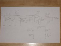
This is what the LM3886 speaker tester amplifier is looking like so far:
I'm going with the datasheet recommended output inductor + resistor for now, since I don't understand enough to change these parts.
Attachments
pmbrunelle,
Good work.
And good point about the low series filter resistance!
You would get better performance with more, but smaller, PSU caps, instead of two big ones, per rail. And if you can't cluster those PSU reservoir caps very near to the power pins of the chipamp, you would also need a substantial capacitance near the chipamp pins. The 0.1 uF X7R should be ON the pins, within a couple of mm of the chipamp's case. Otherwise, you might as well omit it.
I am not one who is aghast when ceramic caps are used. But for the pF caps, I would tend to want to use film caps.
The most-important thing will be the actual layout. It will probably have far more effect on the sound quality than the types of components used. You want to use star grounding, and you want to have no geometric area enclosed by any loops, if possible (it's not, but absolutely minimize it). Otherwise you make antennas. So ALL wire pairs will need to be tightly twisted and all PCB trace pairs need to stay as close together as possible, everywhere, or be opposite each other on a two-sided board. It would be best to use a ground plane and plane-like power distribution. You want the chipamp pins to see the lowest-possible inductance, and impedance in general (ergo, multiple smaller caps in parallel, for decoupling caps as well). Keep the signal ground or ground plane separate, though, with its own separate conductor all the way back to the star ground at the PSU output ground.
Sorry if you know all of that already. You also want the layout around the chip to be very compact. Any component that connects to a pin should be right at the pin, to minimize parasitics (and antennas).
There are two great things in the post at the following link. One is a post by airwulf, saying everything I am trying to say, and another is the set of links at the bottom, to the famous Terry Given's posts about a capacitor bank. My next build will have two cap banks like that (one per rail), and an amp on a small PCB a couple of mm above where the cap banks meet, so that the power and ground pins can go directly to either side of the cap bank PCB.
http://www.diyaudio.com/forums/chip-amps/224914-lm3886-component-selection-3.html#post3282640
You could easily wind your own air-core output inductor. But do not wind the inductor around the 10-Ohm resistor. See Pronine Electronics Design - Multilayer Air Core Inductor Calculator .
You might also want to calculate the upper and lower bounds of the reservoir capacitance that is needed. The equations are in the post at:
http://www.diyaudio.com/forums/chip-amps/152471-finalizing-tda2050-lm3886-2.html#post3363511
In a post right after that one, there is a link to an Excel spreadsheet that will simulate your power supply, with transformer and relevant transformer parasitics, and an almost-worst-case load. It actually solves the differential equations (different ones, depending on diode conduction state). But it probably doesn't account for efficiency very well, so you might want to find the minimum VA transformer rating with it, then, multiply that by three or so. You will probably also want to use a higher Vrms output voltage rating than you thought, and just limit the output power by design (maybe in a volume pot circuit?), or at least say its max power rating is lower than the rails would imply. Otherwise, unless the reservoir capacitance is excessive, it will be difficult to have sufficient headroom to make the amp "bulletproof"-enough.
Cheers,
Tom
Last edited:
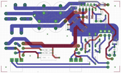
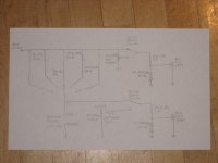
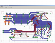
Well, while I'm at it, I might as well show the PCB layout, and the rest of my speaker tester schematic, so the PCB will make some sort of sense.
I'm working with the freebie version of EAGLE, so that's why some things are drawn in MS-Paint; the free version is limited in terms of board area, so some components aren't there, pads just represented with vias. And the mounting holes also look like vias; this is so their position gets transferred to the copper when I do the toner transfer. Soooo, excuse the hackjobbery!
It will be dual layer (my first😀), but there are some limitations, such as no thru-plated holes, and the bare copper traces on the top have to be routed where they won't accidentally short component leads, etc.
With the current layout now, the ceramic PSU caps are ~13 mm away from the chip pins. And that's not including the lead lengths! Is leaving potentially ineffective ceramic caps a don't care thing (if they do no harm, I'll leave them for the feel-good feeling), or is it a bad recipe for resonance issues with the large electrolytics, in which case, they won't be included.
The focus on loop areas is really a convenient trick. At the end of the day, the only things that can affect a wire are the electromagnetic fields at the wire. However, there's Stokes' Theorem from calculus, which relates what's happening within the loop area to what's happening along the closed loop. Saves us some brain-scratching, and gives us a simple rule of thumb to follow (minimize loop area).
I get that's there's the rule of thumb to minimize loop areas. My problem is a fundamental lack of understanding of electricity and magnetism. This makes reducing loop areas difficult. My speaker tester here has maybe ~30 nodes (I didn't bother to count them). With 30 nodes, I could probably draw over 100 unique current loops, maybe more? I'm not sure which loops are important, and which ones are not. Minimizing the area of one loop increases the area of another...
So which loops are important? I realize I won't gain my own judgement for this overnight...
In general though, I tried to arrange so that the sum of currents in any wire bundle is zero.
I just did the rough PSU ripple calculation, assuming the capacitors get recharged at 120 Hz (60 Hz full-wave rectified), and that the diodes only conduct for a short time at the peaks.
If I'm drawing a constant current (makes for the nice linear discharge curve, yay for high-school math!) of 7A (LM3886 max current limit), then I'll have 5.2 V peak-to-peak of ripple (on one rail). It's a lot of ripple, but that's not a normal operation condition, that's an abuse condition that should just be semi-survivable, and the 2x 4A ripple current rated electrolytics should handle that. Plus I have the EAGLE board real-estate problem 😡 Oh well, can't complain, given what I paid for it.
I looked at your transformer spreadsheet, and since I'm not going to understand it anytime soon (a lot of numbers, everywhere), I'll just post now instead...
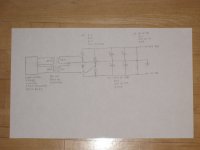
Description of the speaker tester (for use with Speaker Workshop, but possibly other software):
Signals from a computer sound card output are buffered by an LM3886 power amplifier.
Two basic functions:
1. Measure the impedance of speakers and stuff using a voltage divider with a known series resistance. The two unknown voltage divider nodes are measured by the sound card's left and right inputs, so the unknown impedance can be solved.
2. Take acoustic measurements. While playing a signal through a speaker, capture the acoustic response with a microphone (I have a separate pre-amp). The left soundcard input measures the amplifier signal, and the right input measures the acoustic signal. Comparing the two, the speaker's acoustic response can be measured.
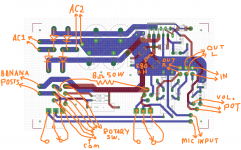
Note: there are three unlabelled solder pads near the middle bottom of the board. This is for the 100 ohm pot.
I'm working with the freebie version of EAGLE, so that's why some things are drawn in MS-Paint; the free version is limited in terms of board area, so some components aren't there, pads just represented with vias. And the mounting holes also look like vias; this is so their position gets transferred to the copper when I do the toner transfer. Soooo, excuse the hackjobbery!
It will be dual layer (my first😀), but there are some limitations, such as no thru-plated holes, and the bare copper traces on the top have to be routed where they won't accidentally short component leads, etc.
With the current layout now, the ceramic PSU caps are ~13 mm away from the chip pins. And that's not including the lead lengths! Is leaving potentially ineffective ceramic caps a don't care thing (if they do no harm, I'll leave them for the feel-good feeling), or is it a bad recipe for resonance issues with the large electrolytics, in which case, they won't be included.
The focus on loop areas is really a convenient trick. At the end of the day, the only things that can affect a wire are the electromagnetic fields at the wire. However, there's Stokes' Theorem from calculus, which relates what's happening within the loop area to what's happening along the closed loop. Saves us some brain-scratching, and gives us a simple rule of thumb to follow (minimize loop area).
I get that's there's the rule of thumb to minimize loop areas. My problem is a fundamental lack of understanding of electricity and magnetism. This makes reducing loop areas difficult. My speaker tester here has maybe ~30 nodes (I didn't bother to count them). With 30 nodes, I could probably draw over 100 unique current loops, maybe more? I'm not sure which loops are important, and which ones are not. Minimizing the area of one loop increases the area of another...
So which loops are important? I realize I won't gain my own judgement for this overnight...
In general though, I tried to arrange so that the sum of currents in any wire bundle is zero.
I just did the rough PSU ripple calculation, assuming the capacitors get recharged at 120 Hz (60 Hz full-wave rectified), and that the diodes only conduct for a short time at the peaks.
If I'm drawing a constant current (makes for the nice linear discharge curve, yay for high-school math!) of 7A (LM3886 max current limit), then I'll have 5.2 V peak-to-peak of ripple (on one rail). It's a lot of ripple, but that's not a normal operation condition, that's an abuse condition that should just be semi-survivable, and the 2x 4A ripple current rated electrolytics should handle that. Plus I have the EAGLE board real-estate problem 😡 Oh well, can't complain, given what I paid for it.
I looked at your transformer spreadsheet, and since I'm not going to understand it anytime soon (a lot of numbers, everywhere), I'll just post now instead...
Description of the speaker tester (for use with Speaker Workshop, but possibly other software):
Signals from a computer sound card output are buffered by an LM3886 power amplifier.
Two basic functions:
1. Measure the impedance of speakers and stuff using a voltage divider with a known series resistance. The two unknown voltage divider nodes are measured by the sound card's left and right inputs, so the unknown impedance can be solved.
2. Take acoustic measurements. While playing a signal through a speaker, capture the acoustic response with a microphone (I have a separate pre-amp). The left soundcard input measures the amplifier signal, and the right input measures the acoustic signal. Comparing the two, the speaker's acoustic response can be measured.
Note: there are three unlabelled solder pads near the middle bottom of the board. This is for the 100 ohm pot.
Attachments
Last edited:
The important loops to minimize are:
1. The AC mains pair
2. The secondary pairs
3. The rectifier output pair(s)
4. The input signal and ground pairs
See Faraday's Law (Maxwell's Equations).
The first three will transmit and the fourth one will receive.
1. The AC mains pair
2. The secondary pairs
3. The rectifier output pair(s)
4. The input signal and ground pairs
See Faraday's Law (Maxwell's Equations).
The first three will transmit and the fourth one will receive.
With some thought, Ive decided that 11200 uF per rail wasn't really adequate. Too much droop, especially given the (low) +/- 20 V rails, so I revised this to 30000 uF per rail (3X 10000 uF). The board dimensions grew slightly.
20 V sounds low, but it's in case I decide to connect a 2 ohm speaker, or decide to apply a rail-to-rail square wave to any of the resistors connected to the LM3886's output; the resistor power ratings necessary become excessive. The idle heat dissipation also goes down with lower voltage supplies.
I modified the traces around the bridge rectifier to reduce loop area there. I suppose a one-piece rectifier is better in terms of stray magnetic fields, but after a certain current level, they need a heatsink, which is a pain in the butt. With the exposed surface area of 4 discrete diodes, you can rectify more current before needing to worry about heatsinking.
<< picbuck said: Wiper position doesn't affect the impedance seen by source. It does affect the impedance seen by the LM3886, but in this case that doesn't matter. >>
http://www.diyaudio.com/forums/atta...tda2050-mixer-amp-help-tda2050_d_3b_iview.jpg
<< gootee replied: A TL071-family opamp is a FET opamp, so its inputs don't draw much current. Quite different than an LM3886. ----- The LM3886 bipolar inputs can draw up to 1 uA. Through a 50k resistance, that's up to 50mV of DC offset at your input, which will diminish to zero as the wiper touches ground! >>
picbuck continues:
Yes you're right, and with a gain of 20 that would be a possible DC offset of a full volt at the speaker terminals. Not something to shoot for.
However, enter Ci, which is included in both the National, and Texas Instruments, schematics. This otherwise-unneeded capacitor is included to take care of exactly the situation you mention: it sets DC gain to unity. Thus output offset will be the same as input offset.
Of course, this still leaves the output offset at a possible 50mV, which is not a great design goal. Most people would like something closer to 10mV, or better still none. But I just wanted to follow through on your thought.
Yes, you continued with my thoughts pretty well!
There are many ways to attack an issue, but once you're aware of it, then you can make a more educated decision on what to do.
Another consideration, the LM3886 can also have an input offset voltage of up to 10 mV, which will be multiplied by the DC gain of your circuit.
There are many ways to attack an issue, but once you're aware of it, then you can make a more educated decision on what to do.
Another consideration, the LM3886 can also have an input offset voltage of up to 10 mV, which will be multiplied by the DC gain of your circuit.
With a DC blocking capacitor in the NFB loop the DC gain is 1.
The output offset is roughly equal to the input offset.
I and this is very personal, would look at experimenting with the input filters. I set them as close as possible to the audio pass band such that they cannot be heard and no closer. RC = 0.68us & 90ms
Some prefer the filters to be set much wider than my preference. I recommend you find your preference.
Just bolt the bridge rectifier to the chassis, either the floor or the side/back depending on where your transformer wires are. If the rectifier becomes hot powering a ClassAB amplifier then you have wired something up incorrectly............... a one-piece rectifier ............. after a certain current level, they need a heatsink, which is a pain in the butt. With the exposed surface area of 4 discrete diodes, you can rectify more current before needing to worry about heatsinking.
- Status
- Not open for further replies.
- Home
- Amplifiers
- Chip Amps
- Normal input impedance values