
The beauty of this is not only can you choose the resistor type and tolerance.
But you can also change the (log-like) taper to suit your own requirements.
Patrick
But you can also change the (log-like) taper to suit your own requirements.
Patrick

Our reason for DIY.
Something you just cannot buy, because no manufacturer would make something like this.
😉
Patrick
Something you just cannot buy, because no manufacturer would make something like this.
😉
Patrick
 The pics are from my build and I'm very glad to have been part of this small GB. The pre amp build is almost finished, only the Xen designed PSU and signal transformers for the LM3915 bargraph PCB are still misssing. Now there’s just a temporary 4V LM317 PSU.
Yes, only 5 lucky guys in this private group project.
Shared costs, no profit.
GB for unobtanium Cinemag 15/15 PCB version.
😉
Patrick
Shared costs, no profit.
GB for unobtanium Cinemag 15/15 PCB version.
😉
Patrick
I was asked about component choice and circuit layout compared to some other DIY preamp projects with transformers and buffers.
1. Where to put the buffer ?
We want the preamp to be able to drive cable capacitances as well as 10k load impedance with low distortion.
In particular, we want to be able to use a balanced inverting power amp downstream (e.g. an Aleph-X).
It is, IMHO, a much better choice to place the buffer after the transformer / attenuator.
This is also the reason why we have a buffer at all, instead of pure passive.
2. Why 10k:10k transformer and not 600R:600R ?
There are quite a few very nice 10k:10k transformers with very low distortions at line level.
They are a much easier load to drive than 600R, and you can place a 10k attenuator at the output for optimum load.
Any modern signal source will have low enough output impedance to drive a 10k load through these transformers without need for extra buffer upstream.
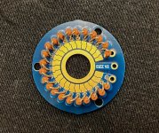
3. Why EIZZ for attenuator ?
The layout allows any commercial attenuator to be used, whether switched or not.
We stripped open one of those attenuators with white-and-blue plastic rotary switches to check them out.
And we decided that the EIZZ has much better switch contacts than those, and still at reasonable price.
Other switches like DACT or Elma are even better switches, but more expensive.
For a switched attenuator, the quality of switch is just as, if not more, important than the resistors, in added distortion.
It is very difficult to guarantee consistent contact resistance in switches for low current applications (as in line-level audio).
4. Why Elma rotary switch for source select, instead of relays ?
Same reasons as above -- quality of low-signal-current switching.
There are only a couple of relays from the entire catalog from Omron that we consider suitable.
And of course a rotary switch is much simpler than 6 relays (for 6 sources), a power supply and still needing a rotary switch.
But the most important is the switch contact resistance at low current.
5. Why not shunt regulators ?
We had bad experiences with shunt regulators; they tend to oscillate with complex loads.
The JFET buffers we used have high PSRR, so fancy regulators has much less benefit.
We consider a two-stage regulation, with Tx and first regulator 1m away, to be more beneficial.
See also the regulator shoot-out at Linear Audio :
https://linearaudio.nl/sites/linearaudio.net/files/v4 jdw.pdf
The winner is a series regulator, not shunt.
6. Why dual 2SK209 buffer and not 2SK170/2SJ74 ?
2SK209 is an active part and you do not have to pay 10USD a piece, in fact << 1USD.
In our published measurement, 2x 2SK209GR // are just as good as a single 2SK170.
So for the simple JFET buffer at least, this is our choice.
There are other applications where the complementary pair is essential, but not here.
https://www.diyaudio.com/community/threads/njfets-for-source-follower-applications.329131/
https://www.diyaudio.com/community/...rce-follower-applications.329131/post-6931537
Of course, only my personal choice.
Cheers,
Patrick
1. Where to put the buffer ?
We want the preamp to be able to drive cable capacitances as well as 10k load impedance with low distortion.
In particular, we want to be able to use a balanced inverting power amp downstream (e.g. an Aleph-X).
It is, IMHO, a much better choice to place the buffer after the transformer / attenuator.
This is also the reason why we have a buffer at all, instead of pure passive.
2. Why 10k:10k transformer and not 600R:600R ?
There are quite a few very nice 10k:10k transformers with very low distortions at line level.
They are a much easier load to drive than 600R, and you can place a 10k attenuator at the output for optimum load.
Any modern signal source will have low enough output impedance to drive a 10k load through these transformers without need for extra buffer upstream.
3. Why EIZZ for attenuator ?
The layout allows any commercial attenuator to be used, whether switched or not.
We stripped open one of those attenuators with white-and-blue plastic rotary switches to check them out.
And we decided that the EIZZ has much better switch contacts than those, and still at reasonable price.
Other switches like DACT or Elma are even better switches, but more expensive.
For a switched attenuator, the quality of switch is just as, if not more, important than the resistors, in added distortion.
It is very difficult to guarantee consistent contact resistance in switches for low current applications (as in line-level audio).
4. Why Elma rotary switch for source select, instead of relays ?
Same reasons as above -- quality of low-signal-current switching.
There are only a couple of relays from the entire catalog from Omron that we consider suitable.
And of course a rotary switch is much simpler than 6 relays (for 6 sources), a power supply and still needing a rotary switch.
But the most important is the switch contact resistance at low current.
5. Why not shunt regulators ?
We had bad experiences with shunt regulators; they tend to oscillate with complex loads.
The JFET buffers we used have high PSRR, so fancy regulators has much less benefit.
We consider a two-stage regulation, with Tx and first regulator 1m away, to be more beneficial.
See also the regulator shoot-out at Linear Audio :
https://linearaudio.nl/sites/linearaudio.net/files/v4 jdw.pdf
The winner is a series regulator, not shunt.
6. Why dual 2SK209 buffer and not 2SK170/2SJ74 ?
2SK209 is an active part and you do not have to pay 10USD a piece, in fact << 1USD.
In our published measurement, 2x 2SK209GR // are just as good as a single 2SK170.
So for the simple JFET buffer at least, this is our choice.
There are other applications where the complementary pair is essential, but not here.
https://www.diyaudio.com/community/threads/njfets-for-source-follower-applications.329131/
https://www.diyaudio.com/community/...rce-follower-applications.329131/post-6931537
Of course, only my personal choice.
Cheers,
Patrick
Last edited:
How can you build something like this without the mechanics ?
Well, if you want truely dual mono as we do, you can't, unfortunately.
Unless you make the compromise and live with 4 knobs.
A compromise would be a 4-gang pot (for balanced) and 2 rotary switches for 3 knobs.
But there is less separation between channels at the pot, unless the pot is well shielded between gangs.
Patrick
- Home
- Amplifiers
- Pass Labs
- NoQuiPas -- A Truely Dual-Mono, Fully-Differential Passive Preamp with Output Buffers