Hi, Pocoyo! 🙂
I'm using Vishay Dale RN60D resistors, Nichichon Muse Fine Gold electros, and Wima polyester.
The 5W resistors are KOA metal plate (I think non inductive)
I'm in the process of reassembling the amp, soon I'll post pictures.
Regards,
Paulo.
I'm using Vishay Dale RN60D resistors, Nichichon Muse Fine Gold electros, and Wima polyester.
The 5W resistors are KOA metal plate (I think non inductive)
I'm in the process of reassembling the amp, soon I'll post pictures.
Regards,
Paulo.
try to change the caps if you have more budget
BG std will be good too for 100uf/100v
btw
- what caps supply you use for this ?
- what bypass caps you use for this?
if you have better solder wbt or mundorf AGAU
you can suction the old solder in signal rails first
if become better go to supply rails too
BG std will be good too for 100uf/100v
btw
- what caps supply you use for this ?
- what bypass caps you use for this?
if you have better solder wbt or mundorf AGAU
you can suction the old solder in signal rails first
if become better go to supply rails too
Last edited:
I agree that mosfets do sound more brighter in mids and highs than bipolars but then again they are weaker sounding in the bass region, pick your poison....
Not necessarily, it depends on the rest of the circuitry.
It could sound bright because it simply has a wide bandwidth.
Harshness could come from distortion in the amp.
Needs checking with a spectrum analyser or a distortion meter.
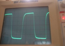
I dissagree. Wide bandwidth of the transistor or the amplifier should not have this affect. My current mosfet project is quite fast, -3dB gain is >500KHz. It does not sound harsh at all. This photo is of 100KHz sqr wave, 30Vp @ ~4.5R.
Attachments
Last edited:
Someone please check my quiescient current. It gives me 26A across R37!
Am I seeing this right? (I used 0V for the input voltage signal).
Thank you.
Am I seeing this right? (I used 0V for the input voltage signal).
Thank you.
I'm not sure if I am measuring bias current the right way but I put Vin to zero and watched the current across an emitter resistor. Now I think it's biased at 220mA. I see no signal of oscilation in the FFT plot. Of course, I might be wrong. I'm still suffering from noobiness. 😉
I ask if someone could see my sym and tell me if it's ok this way, or if there's still oscilation or anything else imparing this circuit that I'm too noob to see. I attach the schematics.
Thank you.
Regards,
Paulo.
I ask if someone could see my sym and tell me if it's ok this way, or if there's still oscilation or anything else imparing this circuit that I'm too noob to see. I attach the schematics.
Thank you.
Regards,
Paulo.
Here is the schematics from LTSipe:
Take the models you are using and paste them as a comment right on the main body of the simulation. OR, create a text file "pooge2.txt" and paste your specific models there , then ... add .include pooge2.txt as a spice directive.
OS
OK, Is atached to this post.
Thank you! 🙂
Its fine in this new sim, no problems, in this interation this amp has a fine THD spectrum, what are all the changes here compaired to the original, only the output mosfets and the bias resistor of the drivers ???
Whats the reason for the change to the irf Fets, with the toshibas youll get much better performance and for some reason they sound better as well. You also really dont need 0.47 ohms accross the emitter resitors, youre losing a lot of power, 0.22 ohms is fine. 100ma bias is more than enough for these mosfets, you gain very little with higher bias except for getting a higher electricity bill at the end of the month.
100ma bias is more than enough for these mosfets, you gain very little with higher bias except for getting a higher electricity bill at the end of the month.
I get away with 30mA per MOSFET pair with IRFP240/9240.
Its fine in this new sim, no problems, in this interation this amp has a fine THD spectrum, what are all the changes here compaired to the original, only the output mosfets and the bias resistor of the drivers ???
Whats the reason for the change to the irf Fets, with the toshibas youll get much better performance and for some reason they sound better as well. You also really dont need 0.47 ohms accross the emitter resitors, youre losing a lot of power, 0.22 ohms is fine. 100ma bias is more than enough for these mosfets, you gain very little with higher bias except for getting a higher electricity bill at the end of the month.
Mostly fine , just 1 little discrepancy (below). one plot is with the 20pf lead compensation , the second is without. Any opinions ??
OS
Attachments
Whats the reason for the change to the irf Fets, with the toshibas youll get much better performance and for some reason they sound better as well. You also really dont need 0.47 ohms accross the emitter resitors, youre losing a lot of power, 0.22 ohms is fine.
The reason is I couldn't find the 2sk1530/2sj201 spice model and because I have some irfs in my parts bin I decided to try them on LTspice.
Thank you all for the help you are providing to me. You are very kind!
Last edited:
is there a way to compensate out the dip in phase from 20kHz to 1MHz?
It would sure look nice if it were 90degrees +-10degrees over that frequency range.
Would it behave better?
would it sound better?
It would sure look nice if it were 90degrees +-10degrees over that frequency range.
Would it behave better?
would it sound better?
Good to ear that! 🙂ts fine in this new sim, no problems, in this interation this amp has a fine THD spectrum, what are all the changes here compaired to the original, only the output mosfets and the bias resistor of the drivers ???
Yes, the changes from the original are the irf mosfets and playing around with the bias resistors of the drivers. Seems low value gives better sound.
That would be interesting. I would raise the 20pf cap but what would happen to slew rate? Is there a way to get the slew rate from LTSpice?is there a way to compensate out the dip in phase from 20kHz to 1MHz?
It would sure look nice if it were 90degrees +-10degrees over that frequency range.
Would it behave better?
would it sound better?
The good news is harshness is gone. 🙂
The bad news is the mids are not so great.
I've been swapping the Toshibas and the Irfs and this is my findings:
Toshibas: Bass is thundering! Strong, precise, very sharp and detailed. My bookshelf speakers sound like they were floorstanders!
The highs are good, no more harshness, and also detailed.
The mids are problematic. Voices sound like I have an equalizer attenuating the mid frequencies or the singers are singing away from the microfone.
IRFs: Very good mids. Sweet juicy voices, specially the female voices sound very good, even lusty. Like the nad or the SKA.
The bass is not as tight as with the toshibas and it's kind of muddy, not having sharpness. The highs are Ok, not great but decent.
So, what do I do? Loose the bass and treble for the mids or vice-versa? Any ideas in improving the sound?
Thanks!
Regards,
Paulo.
I'll will experiment with that. Thanks.You could try increasing the feedback DC blocking capacitor to help the IRFs.
Does someone has the spice models for 2sk1530 and 2sj201 ? Can't find it anywere...
You should read an1645 from national, google for it, then experiment with the gate resistors, for the toshibas try smaller values 100ohm and about 50 ohm, these have an inpact on the sound too. From the an1645 application note you can learn what this does to the wave response.
- Status
- Not open for further replies.
- Home
- Amplifiers
- Solid State
- Noobie needs help on ebay amplifier