Hi guys, I'm very happy to have stumbled across this forum. I've had fun with car audio for a little while now, and have decided I want to fix an amp that I recently acquired. It is a diamond audio d5 600.4. channels 3 and 4 play cleanly, but I get no output other than a very faint hiss from channels 1 and 2.
The power supply obviously works, as channels 3 and 4 produce output, and the rails show +30v and -30 volts, and the +15v and -15v sections also check out.
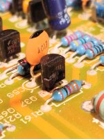
I do see what look like two blown resistors in the channel 2 section, and w resistors that look like they are blackening, but resistance still checks out in channel 1.
I have been testing the output transistors with a multimeter in diode mode, and don't think I have any failed ones.
Why would those resistors burst on channel 1 and 2?
I'm a bit of a noob, but I can follow directions pretty well. Hoping to fix this thing and see how it sounds...
The power supply obviously works, as channels 3 and 4 produce output, and the rails show +30v and -30 volts, and the +15v and -15v sections also check out.
I do see what look like two blown resistors in the channel 2 section, and w resistors that look like they are blackening, but resistance still checks out in channel 1.
I have been testing the output transistors with a multimeter in diode mode, and don't think I have any failed ones.
Why would those resistors burst on channel 1 and 2?
I'm a bit of a noob, but I can follow directions pretty well. Hoping to fix this thing and see how it sounds...
Attachments

It could have been due to an external fault. Replace them and see if they start to heat up.
Power up through a limiter or low rated fuse and either clamp the transistors down or very carefully monitor their temperature.
Power up through a limiter or low rated fuse and either clamp the transistors down or very carefully monitor their temperature.
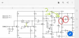
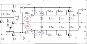
Thanks for the response. I have found the two offending resistors in the schematic. Should I be concerned about the two transistors leading up to the resistors? Why would only the two on the positive rail side burnt up?
Thanks. I'll be trying to pick up some resistors tomorrow. 220ohm and 100 ohm.
Thanks. I'll be trying to pick up some resistors tomorrow. 220ohm and 100 ohm.
Attachments
You should at least check the transistors in the circuit to confirm that none are shorted.
Where did you get the diagram? I didn't see the 600.4 on the site I checked.
Where did you get the diagram? I didn't see the 600.4 on the site I checked.
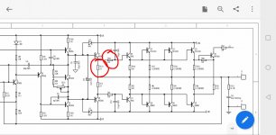
I didn't find the 600.4 diagram. I found the 300.4 and 600.2 diagrams. I checked the input section based off the 300.4, and when it goes to ch1pwrin to the output section, I referred to the 600.2 diagram. The output layout of the 600.2 has 6 output transistors per channel, to the 600.4 4 per channel. I got the diagrams from elektrotanya.
I will picking up some resistors and transistors today at the store, they don't have the 221 ohm resistor, but they do have a 220 ohm resistor. If I replace both, it should work ok, I think... good thought process? Or severe misunderstanding of how the circuit works?
Also, they do have the correct blown transistor, the (q37 in the diagram) MPSA56 for the negative side of the wave, but for the top part, (q29 in the diagram) they do not have the MPSA06. They do have both of the items specified on the diagram though, the TIP41C and TIP42C. Those are the transitors specified for the d5 600.2, while the MPS items are what came in those locations for the d5 600.4. They seem to be just larger beefier transistors. Would they cause a problem in the 600.4? I could also replace Q8 at the end of the circuit.
Anyway, plan is replace resistors, replace one toasted transistor, see if it works, if it does, then try the bigger transistors and see what happens. 😀
Thanks again.
Attachments
The larger drivers are probably used because the output stage has more transistors to drive. The TIP drivers may work but could also case problems if the circuit has any other differences. You'd need a scope to confirm that the drivers are working properly in the circuit.
The pin configuration is different so you'd have to twist or otherwise reconfigure the leads to make the TIP drivers fit.
I'd suggest ordering the right parts (not from ebay).
The pin configuration is different so you'd have to twist or otherwise reconfigure the leads to make the TIP drivers fit.
I'd suggest ordering the right parts (not from ebay).
I've gotten the right transistors and resistors, as well as the larger tip4x transistors. I am going to get all the bits installed tonight.
Well the above post didn't add much to the thread. I did get some sound to come out of channels 1 and 2, but it sounds very poor. Lots of scratching and popping, and certain output transistors heat up more than the rest. I got the replacement transistor installed. It was not a mpsa56 like the orignal, it was a nte159. The guy at the electronics store said it was a drop in replacement, a little Google action convinced me that it was.
I replaced several 100 ohm resistors that had appeared discolored, or popped, as well as a couple of 221 ohm resistors.
When I put an audio signal to channel 3 or 4, it comes out loud and clean. When I send an audio signal through channel 1 or 2, it sounds scratchy or popping. Badly. If you fiddle around with the gain knob, it will do a bit better as you turn it higher. It also is low volume. All output transistors check out, as do all of the smaller ones in the individual 1 and 2 channels. The output circuit is exactly the same as the 600.2 one posted, except, 600.2 has the extra output transistors per channel, and the larger driver transistors.
Why would get a lower volume,and lots of scratchiness? Sounds now come out of channel 1 and 2, so that is a little bit of progress.
Here is the weird part. The 2sc5200 output for channel 1 are hearing up, and the 2sa1943 for channel 2 are hearing up more than the other output transistors.
Do you have any DC across the speaker terminals of Ch 1 and 2?
Are you testing with a speaker bridged on 1 and 2?
Are you testing with a speaker bridged on 1 and 2?
I was testing one channel at a time with one speaker at a time. Do I want to look for DC voltage between ch1+ and ch2-? I can check in the am... Thanks.
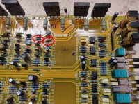
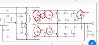
So I have success with channel 1. Bunch of mpsa06 and 56 transistors showed up today, and replacing the circled transistors brought channel 1 back to life. Nice and clean signal. Actual music out of the damn thing. I changed the same items for channel 2, and it did not resolve the issue. There may be other issues further up stream as there was a more catastrophic looking failure on that side. But I am very encouraged.
Resistors circled were replaced on channel 2 as they had burned up. I will be changing out more bits on channel 2 with the hope that it also comes back to life.
Resistors circled were replaced on channel 2 as they had burned up. I will be changing out more bits on channel 2 with the hope that it also comes back to life.
Attachments
There is a tektronics 465 dm 40 model for sale locally for $75. Looks a little rough, but guy says it works.
If in good working order, the 465 is a wonderful scope. I paid $500 for a 465B with the DM44 about 15 years ago and although I had many other scopes, I preferred and used that one. $75 for a 465 in good working order (even if it looks like it was run over by a tank) is a bargain.
So I got all 4 channels working on the rest bench. All 4 channels will play a 60hz test signal from phone. Gains for 1 and 2 behave as expected, increasing the voltage at the speaker outputs. The signal sounds clean on all 4, and the main output transistors seem to all warm up at the same rate based on my advanced finger probe. Before 3 and 4 behaved this way, but channel 2 did not. I didn't do any extended testing, but it will last at half gain setting through a whole song and the output transistors are all uniformly mildly warm, and the music sounds clean. Tomorrow I plan on sticking it back in the heat sink and testing louder in the garage. It is only hooked up to a 13v 30amp max power supply. If it passes it that test, I'll throw it in my car and giver a go.
Perry, thank you for your help. I enjoyed the process so far, and will likely look for another class ab amp to fix.
Perry, thank you for your help. I enjoyed the process so far, and will likely look for another class ab amp to fix.
- Home
- General Interest
- Car Audio
- Noob diamond audio d5600.4 no output on channel 1 and 2