Any reasonable output base stopper makes essentially no difference to the VAS Non-MP behaviour.
Perhaps, but it definitely affect the stability of the amplifier, about the same as your claimed RHP. With common 2.2ohm base stoppers, the phase margin degrades (compared to 18 ohm) by about 6 degrees (which is not a big deal) but the gain margin lowers from some 6dB to some 3dB, which is a big deal. Therefore, it doesn't make any sense to analyze something that is compromised (from a stability perspective) to start with, and needs 18 ohm base stoppers to get a decent gain margin. BTW, speaking about a practical perspective, those 18 ohm are, very likely, making the whole amp thermally unstable.
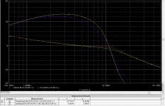
The ULGF of the amp in your asc is ~3MHz (much larger than in your plots), but since you did not post the models, this could be related to different models in your LTSpice.
Mr. Zan, if you want anybody to be able to reproduce and comment on your results, you should post your complete and synthetic results, including an exact schematic, models, methodology used to get the results, interpretation, ways to crosscheck the results. Since extraordinary claims require extraordinary proof, the burden is on you to provide coherent and complete information to start with. Then others may pick up, confirm your results and perhaps advance the understanding. Without that, don't be surprised that nobody, except yourself, is buying into your "practical importance of non-minimum phase effects" stance.
P.S. As you can see, the RHP zero is at some 30MHz, which makes sense in a power amplifier with Ft of the same order of magnitude.
Attachments

Last edited:
The base stoppers are set to 4.7R in the current revision since months. But this is old coffee. The amplifier was and is stable with 18 and/or 4.7R base stoppers. And it was always thermally stable!
Turns out that it's sin (wt + pi/4), which sorta makes sense- you get a 90° phase shift for a "whole" derivative, so a half derivative would cause a 45° phase shift.
Yes. My only defence is that it was 2 am over here. Woke up and realised it was incorrect but you already had the answer. Thanks for that.
But the minimum phase still should look like a Hilbert transform..
Yes, no mistake there.
Best wishes
David
Last edited:
about 1/2 way thru http://www.ece.jhu.edu/~pi/Courses/454/Notes8.pdf is a few pages more
This crashes my Chrome browser about half way thru, just at the start of the best bit.
WTF? I don't know how this can even happen.
and this goes a little into nonminium phase http://leo.technion.ac.il/Courses/CT/Lectures/lect02b.pdf
Thanks for that.
but its easy to find statements like:
"The Hilbert transform, in its raw form, is a convolution operator
with kernel cot t2. This is an awkward kernel to handle, just because it is a transcendental function."
I was just about to say that.
Best wishes
David
Last edited:
With common 2.2ohm base stoppers.... Therefore, it doesn't make any sense to analyze something that is compromised (from a stability perspective) to start with...
2.2 ohms stoppers were not in the circuit I posted, they are your choice.
So now you complain about your own selected values! That's actually funny, thanks.
Seriously now, the rest of the amp compensation is obviously tuned to a little more base stopper impedance.
Why did you not use an intermediate value between 18 and 2.2 ohms?
I think this would be obvious even before Toni mentioned 4.7.
Mr. Zan, if you want anybody to be able to reproduce and comment on your results, you should post your complete and synthetic results, including an exact schematic, models, methodology used to get the results, interpretation, ways to crosscheck the results.
Obviously a trade-off in my time versus the value of responses.
Useful responses inspire further effort.
Since extraordinary claims require extraordinary proof
Re-read some Bode yesterday. I didn't remember at the time but I have inadvertently more-or-less restated what he wrote in chapter 18 section 10 "Amplifiers with Excess Phase Shift".
So it's not extraordinary, it's canonical.
...As you can see, the RHP zero is at some 30MHz, which makes sense in a power amplifier with Ft of the same order...
Yes, I think this may be the core of it.
The OPS is where the Non MP behaviour shows first.
Bob Cordell's book has a plot on p. 205 that clearly shows OPS Non MP down as low as 2 MHz (slower transistors than Toni) and he even comments on this fact.
The "VAS" alteration in Toni's amp should lower the VAS output impedance and this reduces the effect of the OPS Non MP behaviour.
I don't yet fully understand this OPS Non-MP behaviour, have to re-read Feucht and Cherry.
Any other references or ideas appreciated.
Best wishes
David
Last edited:
- Status
- Not open for further replies.