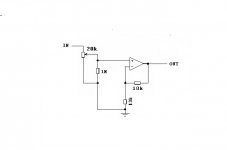
Hi. I want to put a non inverting op amp (gain=2) at the output of my crossover (need a bit of gain for LF). Just want to check if my diagram is ok.
Thanks
Pierre
Remember the local bypass caps.
Use a FET input opamp, so the input current will be very low.
Any suggestions?
Schematics
For schematic see post 1.
Opamp choice I will leave to others - it depends largely on some combination of exact application, cost and fashion.
Opamp choice I will leave to others - it depends largely on some combination of exact application, cost and fashion.
What is the purpose of the 1M resistor? It is fed from the wiper of a 20k pot and will not have any effect, unless the pot goes faulty of course. I would use a TL072 for stereo or as Mooly recomends a TL071 for mono.
"unless the pot goes faulty of course"
That is the point! Not just faulty, but pots get noisy and even a brief open-circuit can produce a lot of noise at the amp output.
1M is a bit high, though. A 10K pot and 100K resistor would be a bit better.
That is the point! Not just faulty, but pots get noisy and even a brief open-circuit can produce a lot of noise at the amp output.
1M is a bit high, though. A 10K pot and 100K resistor would be a bit better.
This is DC coupled.
So I would have put a 47uF between lower 10k and zero volt line.
If the source has any DC on it you will be multiplying it by 2 and putting that on the output of the op amp.
Also consider coupling capacitor on output.
So I would have put a 47uF between lower 10k and zero volt line.
If the source has any DC on it you will be multiplying it by 2 and putting that on the output of the op amp.
Also consider coupling capacitor on output.
output cap
There is a 10 µF at output of the previous stage (with 1M at ground). Didn't expect to add gain and move it on this op amp.
There is a 10 µF at output of the previous stage (with 1M at ground). Didn't expect to add gain and move it on this op amp.
When using a bipolar input opamp, a coupling cap between pot and 1meg (for which 47k will do easily) would be highly recommended. A FET input part should not require this. I would skip the old TL07x in favor of more modern varieties like TLE207x or OPAx134 though. Do use an output isolation resistor near the output pin (but outside the feedback network), 100 ohms or so should do. Something similar may be useful at the noninverting input.
Source impedance of a 20k pot driven by a low-impedance source is 0-5k, so feedback network is best chosen at about 5k/5k for an impedance imbalance of no more than 2.5k (and output loading of 10k, which is OK). The contribution of input impedance distortion to 10 kHz THD should then be limited to about 0.003% at 7.75 Vrms out and is likely to be swamped by other sources. Not like you'd care much in an application like this.
Source impedance of a 20k pot driven by a low-impedance source is 0-5k, so feedback network is best chosen at about 5k/5k for an impedance imbalance of no more than 2.5k (and output loading of 10k, which is OK). The contribution of input impedance distortion to 10 kHz THD should then be limited to about 0.003% at 7.75 Vrms out and is likely to be swamped by other sources. Not like you'd care much in an application like this.
Thanks for all your inputs. However, I'm not sure about the "47k" coupling cap at 20k pot. Is it bad typo or 47000 µF?
I suspect the 47k refers to the resistor in that it could be as low as 47k (instead of 1meg) when used with a 20k pot.
The cap needs to be at least 1uf in size.
The cap needs to be at least 1uf in size.
The effect of the resistor (apart from providing continuity in the event of the pot wiper being intermittent) is to alter the "law" of the pot.
See "Changing the law of a pot" near the bottom of the page here,
Potentiometers (Beginners' Guide to Pots)
The cap needs to be large enough not to impede low frequencies.
See "Changing the law of a pot" near the bottom of the page here,
Potentiometers (Beginners' Guide to Pots)
The cap needs to be large enough not to impede low frequencies.
- Status
- Not open for further replies.
- Home
- Source & Line
- Analog Line Level
- non inverting opamp with gain