Hi folks,
After probably a year of good use of my Hafler 9505, it suddenly got noisy in the right channel. The amp is used for mids/highs in a bi-amp setup. I verified it's the amp by switching the input to the amp with the left channel (noise stayed), and also by hooking up a different speaker (noise still stayed). Exercising the bridging and balanced/unbalanced switches did not make a difference.
When I got this amp, I resoldered some of the more baked solder joints in the high temp areas of the board, but didn't proactively replace anything. I haven't yet opened it up to take a fresh look, as it's at the bottom of a stack of equipment. I'll probably pull it tomorrow. Just wondering whether there were some common failure points in these.
Thanks,
Paul
Swapped the Hafler for the Sumo Andromeda II it had originally replaced. The problem is definitely in the Hafler. Might have to wait a bit to get other projects off my bench before I open it up.
One other weird problem is that I can't get the left side XLR plug to release. The right side released fine, but the left is very stuck in the connector.
One other weird problem is that I can't get the left side XLR plug to release. The right side released fine, but the left is very stuck in the connector.
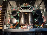
Had a few other things that needed repair, so I got into working on the 9505. Turns out it's a bad main filter cap. Not only doesn't it have any capacitance anymore, but it rattles when you shake it!
Trying to find a proper fit for these caps. Going to call Fosgate tomorrow, in case they sell any parts. Also have a request for quotes out for some CDE DCMX203U100CJ2B from a parts broker. Looks like these are an exact fit.
Had a previous discussion about these back when I didn't need them. Nichicon had some nice snap-ins that looked like they'd be a good fit. Now nobody has them and the lead time is over a year. There are some snap-in CDEs currently stocked at Digikey. I'd rather have screw mount caps, but worst case I'll go with these.
No luck from Rockford/Fosgate. They spun off Hafler to Radial Engineering some years ago, and RE has nothing for pre-2015 amps, other than documentation. The CDE snap-ins are looking more likely...
Will receive the CDE caps tomorrow. These are 5-pin snap-ins - two real pins, and three dummy pins for support. I think I may drill the extra holes in the PC board to allow soldering in the dummy pins as well. Will decide once I have them in-hand.
Installed the new caps today. It was more work than I expected. I decided to cut the extra pins off the caps, rather than drill the boards, but the traces on those boards are so heavy that it took two soldering irons to get enough heat in there to make good solder joints.
So, it's working now, and no more buzz, but I'll need to remove the bottom cover again soon because I'm noticing that the bias is uneven... Much hotter on the right...
The other three caps tested fine, by the way, and two of them rattle when shaken, too.
So, it's working now, and no more buzz, but I'll need to remove the bottom cover again soon because I'm noticing that the bias is uneven... Much hotter on the right...
The other three caps tested fine, by the way, and two of them rattle when shaken, too.
Attachments
- Home
- Amplifiers
- Solid State
- Noisy / crackling output in right channel of Hafler 9505