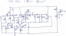
So I'm trying to build a noise gate for guitar based on but not completely the same as other designs. My problem is there's a hum coming in on the rectifier when the sensitivity is at inf. another strange hum signal can be seen after the emitter follower on the rectifier, and thus putts a hum at the drain of the jfet. i cant figure out where this is coming from or how to get rid of it.
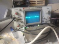
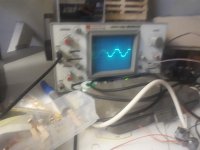
ive attached a diagram. does anything seem off from the get go? ill follow up with pictures of the signal, Vemitter, and Vdrain
ive attached a diagram. does anything seem off from the get go? ill follow up with pictures of the signal, Vemitter, and Vdrain
Attachments
You have worse problems than hum
That FET:
1) has undefined bias (and that´s an understatement)
2) it´s amplifying a HUGE DC signal which will thump big way.
I suggest you do not randomly cut and paste parts from different circuits together to create a new one but build one tried and trusted one.
The most important part of a VCA,including a noise gate, is the controlled gain cell, a nd the one built around that FET is a mess.
The FET must *only* handle feeble Audio and not huge DC.
Upon closer inspection I've realised this is actually a compressor I was going to swap the get to a 2n7000 in the morning. I fail to see any huge dc anywhere my understanding was at 0v in the fet would be biased on (-2v gate-source) and with 100mv in the get would be off 0v gate source with the op amp at maximum gain how is the bias undefined
The hum is probably not related to your circuit, but rather to the attached power supply and amplifier grounding.
I'm not going to fix your circuit design but suggest you work it out in spice. Hint: No DC bias on the FET drain, if you please.
I'm not going to fix your circuit design but suggest you work it out in spice. Hint: No DC bias on the FET drain, if you please.
You're saying I don't need the 9v to the drain? Ok. I'm using a
9v battery and everything's wired on a bread board. Quick question if I don't need to bias the drain what stops the signal clipping like a bjt would. Does it really just act as a voltage controlled resistor? Sorry more familiar with tube/opto circuits
9v battery and everything's wired on a bread board. Quick question if I don't need to bias the drain what stops the signal clipping like a bjt would. Does it really just act as a voltage controlled resistor? Sorry more familiar with tube/opto circuits
Yes but there is more. The gate-source voltage has to go from zero to -pinch voltage for an n-channel. For a single 9V supply you need a p-channel or hang the n-channel source off +9V, not ground.
The range of "variable resistance" is small so think about keeping the signal amplitude low at the FET, and, add 1/2 the audio voltage to the gate so that the resistance is an s curve rather than a c curve. There is a very old National semi article about this, that is probably somewhere on the web. AN-33 analog signal commutation
ftp://bitsavers.informatik.uni-stut...taBooks/1973_National_Linear_Applications.pdf
Sorry, better that should be AN-129 A multiple gain-controlled amplifier.
https://www.amazon.com/LINEAR-APPLICATIONS-HANDBOOK-National-Semiconductor/dp/B001NE07BO
And see
https://www.edn.com/design/analog/4339960/Improve-FET-based-gain-control
https://www.amazon.com/LINEAR-APPLICATIONS-HANDBOOK-National-Semiconductor/dp/B001NE07BO
And see
https://www.edn.com/design/analog/4339960/Improve-FET-based-gain-control
Sorry for the blunt answer but you don´t seem to get it, I´ll have to use stronger words: you have no clue on how a FET is biased but even worse how a Fet attenuator works, so you can´t design a noise gate based on a FET.
Correcting your circuit needs to be so extreme as to fully designing it for you ... I guess that´s not the point
Hint: at the 3k3-3k3 resistors junction audio will be around, say, 200-300mV peak to peak (guitar signal), PLUS a 9000mV to 2000mV swing following audio signal peaks: a mess.
Hint: in general it´s undesireable to have control signal appear mixed with attenuated signal, and if unavoidable, better keep it, say, 60dB below; absolute worst case 40dB below, and that already shows a poor circuit design.
Yours has control signal mixed with Audio, some 20dB (or more), HIGHER than useful audio.
Please just build the Boss Noise Gate this circuit apparently is based on.
Last edited:
Oh ya, You should consider LED+LDR. The LDR does it's own integration-slow to return to high Resistance and it has no amplitude linearity problems. And it eliminates the tricky bias issues.
- Status
- Not open for further replies.
- Home
- Live Sound
- Instruments and Amps
- noise in a noise gate