Hi,
I have an Alientek D8 amplifier. The only problem with the device is continuous noise / hiss, one user used a 15uH inductor between + Vin DC Socket and + Vin 5V DC-DC regulator, apparently it reduced noise almost completely. The question is, isn't it better to use, for example, 200uH or 1mH inductor that will remove more high frequencies?
I have an Alientek D8 amplifier. The only problem with the device is continuous noise / hiss, one user used a 15uH inductor between + Vin DC Socket and + Vin 5V DC-DC regulator, apparently it reduced noise almost completely. The question is, isn't it better to use, for example, 200uH or 1mH inductor that will remove more high frequencies?
I'm sorry but im beginner. I only have information from this post (and thread)
https://www.diyaudio.com/forums/class-d/299580-fda-alientek-d8.html#post5170911
So it operates at 2MHz. I dont think that i can measure capacitance with simple multimeter. But generally, u think that putting inductor should help or it will worse in other thing?
https://www.diyaudio.com/forums/class-d/299580-fda-alientek-d8.html#post5170911
So it operates at 2MHz. I dont think that i can measure capacitance with simple multimeter. But generally, u think that putting inductor should help or it will worse in other thing?
Hi TrueFaith,
Beginner, fine. I found the posting by "audeo". He tried this solution and it seemed to work. I have no reason to state otherwise.
Your assumption is very logical - higher inductance gives better filtering. But, as I wrote before, higher inductance also leaves a higher risk of regulator oscillation. I do not have such an amplifier so I can't try myself and I do not even know what regulator it is or what is the input capacitance used.
If you want to try yourself, I would use an inductor not much bigger than the one used by "audeo", perhaps 22uH or 33uH. Make sure it does not saturate with the current drawn by the 5V voltage regulator.
Good luck with the experiment.
Okay so i have D8 on table and 22uH 4A inductor
"audeo" said
"Input power line" here is the wide lane immediately after the diode at the DC socket and "5V DC-DC" can be seen on the photo as a 6-pin SMD chip marked "IV7GK". See attached some schematic from Aliexpress showing its typical application.
https://www.diyaudio.com/forums/att...ut-6-pin-power-supply-chip-iv7gf-36v-2mhz-jpg
so can you look at my photos?
Alientek - Google Drive
i dont want to destroy my device
In your Google Drive pictures it looks like the device marked SS14 is the catch diode and C36 is the boost diode. The device marked 4R7 is the buck output inductor. You can see that what would be pin six in the picture from audeo is connected to these components where the solder mask is missing. That would mean your left arrow on the Google Drive picture is pointing towards pin 5 which is almost where you want to insert the inductor.
As FF suggests in this case smaller is better. Switching, and linear, regulators can be picky about what you hang on their input and output. C46/C4 appear to be the input decoupling capacitors. Hard to tell but could be in parallel. However they look a bit small to be a total of 4u7. Hard to tell with ceramic chip capacitors. That might cause erratic behaviour if/when you add your inductor. I would go for it but would be wary about possible overvoltage due to undamped ringing. Grumble.
It looks like your target track to cut and place your inductor is the one under 14 of R14. It's not going to hurt if you tag a small electrolytic, 10u-47u across C46/4 and that might tame any possible ringing.
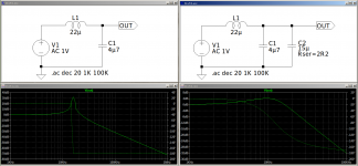
Just to add, if it makes sense, you are creating an LC filter and ideally it should include some form of resistive loss otherwise it will be underdamped and ring. 4A/22u will not have much winding resistance and core losses are probably low. Then you have ceramic capacitors which will have a low ESR, equivalent series resistance. The electrolytic will have a higher ESR and help things out. All said and done its really something you need a scope for.
Burble 22uH and 4u7, assuming C46/4 add up to that, has an impedance, root(L/C), of about 2R2 so you should find an electrolytic with something in that range of value of ESR, it's parallel damping.
As FF suggests in this case smaller is better. Switching, and linear, regulators can be picky about what you hang on their input and output. C46/C4 appear to be the input decoupling capacitors. Hard to tell but could be in parallel. However they look a bit small to be a total of 4u7. Hard to tell with ceramic chip capacitors. That might cause erratic behaviour if/when you add your inductor. I would go for it but would be wary about possible overvoltage due to undamped ringing. Grumble.
It looks like your target track to cut and place your inductor is the one under 14 of R14. It's not going to hurt if you tag a small electrolytic, 10u-47u across C46/4 and that might tame any possible ringing.
Just to add, if it makes sense, you are creating an LC filter and ideally it should include some form of resistive loss otherwise it will be underdamped and ring. 4A/22u will not have much winding resistance and core losses are probably low. Then you have ceramic capacitors which will have a low ESR, equivalent series resistance. The electrolytic will have a higher ESR and help things out. All said and done its really something you need a scope for.
Burble 22uH and 4u7, assuming C46/4 add up to that, has an impedance, root(L/C), of about 2R2 so you should find an electrolytic with something in that range of value of ESR, it's parallel damping.
Last edited:
okay soo last thing.
You think that cutting track is better/easier than soldering directly after some component? Or its the only way?
Audeo did this:
https://www.diyaudio.com/forums/att...587780-fda-alientek-d8-inductor_placement-jpg
But in my opinion cutting track is a little bit brutal
i thought that i can solder inductor with longer cables to IV7JK pin 5 and boost/catch diode pin
Last edited:
It sounds evil but that's the idea. The inductor needs to be in series with the input supply and the regulator so unless there is some other means of breaking the path you have to cut the track. Scrape off the solder mask. Score it through with a scalpel in two places then use your soldering iron to heat up the middle bit whilst gently scrubbing it until it drops off. Tin the two bared ends and add your inductor.
Sorry, just spotted your edit. It looks like audeo has done what I am suggesting, X marks the spot. I've just added a concern about damping.
That does not, Inductor from pin 5 to pin 6, achieve the same result.
Wait for FF to comment. I'm sure I am right but you are wise to be uncertain.
...
Sorry, just spotted your edit. It looks like audeo has done what I am suggesting, X marks the spot. I've just added a concern about damping.
i thought that i can solder inductor with longer cables to IV7JK pin 5 and boost/catch diode pin
That does not, Inductor from pin 5 to pin 6, achieve the same result.
Wait for FF to comment. I'm sure I am right but you are wise to be uncertain.
...
Attachments
Last edited:
Sorry, I was busy with other matters.
MorbidFractal is far ahead of me having an overview of the actual implementation. I studied the photos of the PCB last night but I cannot see how the tracks are running near the small voltage regulator. I could not find a datasheet matching this tiny IC.
You are in a situation where "audeo" states that inserting a 15uH choke will reduce hiss. This is an empiric result, not a logical fact. If the hiss is really annoying, you may take the chance and try yourself.
You will have to cut the relevant PCB track, for a start in one place, scrape off the protective solder mask and for a start connect a 15-33uH choke with short wires (leave insulating plastic below the choke) to the two points of the PCB track. Then you do a quick test if it actually works. If not, remove the choke again and bridge the cut in the PCB track. If it works, mount the choke better in the way described by MorbidFractal.
The source of hiss is generally more complex than just adding inductive filtering to the supply line. However, it can be the supply that is the culprit. My view is that being more certain what is the reason for the hiss will require a circuit diagram and close study of the PCB layout - thus considerably more work.
Last edited:
It looks like your target track to cut and place your inductor is the one under 14 of R14
So you mean that i should put choke on one track, not between two tracks like here?You will have to cut the relevant PCB track, for a start in one place, scrape off the protective solder mask and for a start connect a 15-33uH choke with short wires (leave insulating plastic below the choke) to the two points of the PCB track
https://www.diyaudio.com/forums/att...587780-fda-alientek-d8-inductor_placement-jpg
Im very sorry for my ignorance but i dont know how these all works, i just can ask should i solder it here or there and unfortunately audeo no longer uses this forum
I have some small capacitors (electrolytic) so i can use them to be sure
Last edited:
Ok guys, i'm done with this little boy. When I started work I understood whats going on.
Alientek with 22uH - Google Drive
I glued my inductor on thick plastic plate to the capacitor.
Results:
I got rid of 70-80% of hiss/noise, it was low before so now its inaudible from my chair.
Im very thankful to you all for help and simple explanation
Alientek with 22uH - Google Drive
I glued my inductor on thick plastic plate to the capacitor.
Results:
I got rid of 70-80% of hiss/noise, it was low before so now its inaudible from my chair.
Im very thankful to you all for help and simple explanation
Last edited:
That is a new level of Evil... After the event if you know the output current of the convertor and the input and output voltage then you can calculate the input current as
Iin = Iout*Vout/Vin
The input current is discontinuous but filtered by the decoupling capacitors at the input to the regulator so you can take that as being a ballpark figure for the rating of your new/added inductor. 4A is probably a bit big. You can see it looks a bit big. I mean... it's BIG.
A physically smaller inductor will probably sit on the cut track.
- Status
- This old topic is closed. If you want to reopen this topic, contact a moderator using the "Report Post" button.
- Home
- Amplifiers
- Class D
- Noise, hiss filter - inductor betwen DC socket and 5V DC regulator