Hi!
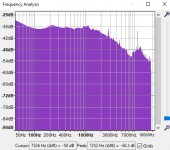
I'm doing a project where I have connected a microphone and an amplifier. It was very noisy before, as can be seen in one of the attached images, but now I have applied low pass filters.
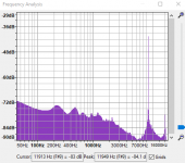
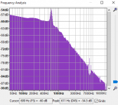
Right now the frequency spectrum looks like the second image (with less noise) but I do not why there still is a peak at around 9kHz?
I've tried to filter both before and after the amplifer, but the noise is always there and with almost the same amplitude.
Can you brainstorm with me, could it be due to bad connection somewhere, bad grounding, wires, computer?
I'm doing a project where I have connected a microphone and an amplifier. It was very noisy before, as can be seen in one of the attached images, but now I have applied low pass filters.
Right now the frequency spectrum looks like the second image (with less noise) but I do not why there still is a peak at around 9kHz?
I've tried to filter both before and after the amplifer, but the noise is always there and with almost the same amplitude.
Can you brainstorm with me, could it be due to bad connection somewhere, bad grounding, wires, computer?
Attachments
When it comes to noise you need to describe the entire chain a bit more detailed.
The 9kHz looks to be about the same strength in both plots indicating it is there in your circuit. Hard to eliminate something that is in your passband. Can be external, from your line, nearby lamp, some modern gizmo, TV, PC, laptop... But being 9kHz you should hear it when you turn stuff off one by one till it disappears. If it's in your circuit somehow, you either find the culprit or live with it. You can attenuate some hard switching frequencies, but if the are there they are there and they cannot be reduced a whole lot.
Anyways, you need to describe your system better, preferably with schematic and even pictures since layout and geometry is important.
Please throw us a bone.Hi!
I'm doing a project where I have connected a microphone and an amplifier. It was very noisy before, as can be seen in one of the attached images, but now I have applied low pass filters.
Which microphone, amplifier, how is it powered. What are these low pass filters and where did you place them? Can't guess these details!!
yes, sorry about that!
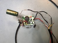
So the microphone is a Panasonic WM61a, the amplifier is called EK022 if you want to search (but i remodelled it a bit), the OP-amp TLC271. It's powered by a power bank with switching supply (guess that's the problem) +5V.
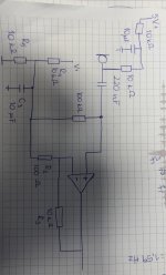
Right know I only placed a low pass filter containing a resistor and a capacitance. I've tried placeing one both just before the amplifier, and also one at the circuit before the resistor that goes directly into the Op-amp. With similar result.
I tried to shorten the circuit so that the mic wasn't connected, but it also gave me the same noise.
So the microphone is a Panasonic WM61a, the amplifier is called EK022 if you want to search (but i remodelled it a bit), the OP-amp TLC271. It's powered by a power bank with switching supply (guess that's the problem) +5V.
Right know I only placed a low pass filter containing a resistor and a capacitance. I've tried placeing one both just before the amplifier, and also one at the circuit before the resistor that goes directly into the Op-amp. With similar result.
I tried to shorten the circuit so that the mic wasn't connected, but it also gave me the same noise.
Attachments
It's powered by a power bank with switching supply (guess that's the problem) +5V.
I think we did come to that conclusion 🙂
Switch mode voltage from power bank, how to filter noise? Use for microphone with amp
You can record the noise on your power supply using Audacity in the same way you record the preamp output. Yu would have to AC couple the 5 volt supply with something like a 10uF and add a 10k or 22k to ground at the output of the cap.
You could then treat the signal across the resistor as a valid audio signal and record it and see what is there. You did scope it and we saw broadband noise.
Hi Mooly!
Correct 😉
Okay, I'll try that, I'm using a TRS cable to connect to a computer, so I'm not exactly sure how to connect these though. What is ground in this case?
Can you describe in more detail how I should connect them? From my power bank I have a black and red cable and in the TRS cable I'm only using TIP and SLEEVE 🙂
Thanks!

To get a baseline try now recording the 'noise' from a 9 volt battery. Exactly the same method and also use the same settings for level etc. I would connect the battery/cap/resistor first before connecting it to your PC. That is just to stop the cap delivering a 9 volt spike to the input.
Also don't lose sight of the fact that you said the amp was quiet on a 9v battery...
Also don't lose sight of the fact that you said the amp was quiet on a 9v battery...
BTW has noone noticed the noise peak is actually at 11kHz, not 9kHz? Could that be a sampling artifact (for instance if sampling at 22kHz or 44.1kHz)?
A (USB) power bank is not a low noise supply. On the contrary, they are genereally very noisy. And with a gain of 40 dB you will get a lot of noise on the output.
The switcher supply in my CS800s amp is enclosed in an earth grounded steel box. Then feed wires to the load are wound a couple of turns around ferrite toroids inside the box.
A ishida food packaging machine (bagger) runs their 220 VAC feed through huge ferrite toroids.
You don't have any inductor in your switcher filter. You don't have a grounded steel box around the switcher supply, either.
Salvage appliances usually have a dead switcher supply in there with ferrite toroids. Even multi speed fans these days. No need to order any. The PS filter toroids I put in my disco mixer came from a dead ATX power supply. Flat screen TV's have big toroids filtering the AC input.
Whenever you are dealing with mic-level signals, a bit of shielding tends not to be a bad idea - the circuit looks awfully inviting to interference as-is. The end of the bias resistor already is part of the high-impedance input node. On the output side, white in the 3-conductor cable is signal and black is ground, with yellow unused? That doesn't look like proper audio cable to me but should do in a pinch. I might add a 100 ohm in series with the opamp output so that isn't unhappy with capacitive loading or anything.
I am also of the opinion that a 10k / 10µ / 10k bias from +5 V would not provide adequate current for the capsule, which is designed for 2k2 from +2 V and could draw up to 0.5 mA - 20k from +5 V would mean 0.25 mA of short-circuit (abs max) current. Try again with 2k2 + 2k2 or 2k2 + 3k3 resistors.
I am also of the opinion that a 10k / 10µ / 10k bias from +5 V would not provide adequate current for the capsule, which is designed for 2k2 from +2 V and could draw up to 0.5 mA - 20k from +5 V would mean 0.25 mA of short-circuit (abs max) current. Try again with 2k2 + 2k2 or 2k2 + 3k3 resistors.
Last edited:
- Home
- Source & Line
- Analog Line Level
- Noise from mic + amp even with filters. Why?