Is that true? What about ground bounce? Do you only work on low speed logic?ricaputo said:My back ground is digital where a gnd is a gnd.
No antennas, just impedance. If you make 'separate' circuit loops share a ground then their currents will produce voltages across the impedance of whatever you call a ground connection. The circuit loops are not separate.I am not used to having to run grounds a certain way as if everything is a antenna.
The reservoir capacitor is the first big capacitor in the PSU - the one nearest the rectifier. The -ve is the negative terminal. You need to learn some words. I have no idea what you mean by 'isolated'.I do not understand reservoir capacitor or -ve. So I isolated the 330uf cap with the 47uf cap. Also ran CT to this point.
I thought you showed us a circuit which included instructions for grounds? Maybe I am confused with another thread.There are no instructions at all for circuits or gnd's.
Your a little harsh aren't you. Isn't Diyaudio a place to learn? The poster asked for help and my opinion is he should get it without any negativity that is associated with other audio forums that I will not mention here.
I'm happy you got your problem solved and in the process you learned and will have a better idea of how to do your next project. I learned something also.... I always isolated the input jacks from the chassis and used a 10 ohm resistor from RCA jack to ground. Its always worked for me but now I will use a smaller resistor and see what difference it makes for me. I also never paid too much attention as to the order I soldered my grounds to my buss bar. I will now pay attention to that. However, I haven't had a noise problem possibly caused by the order I placed my grounds on my buss bar.
So, your thread in my opinion was a win, win. Your problem was solved and information was exchanged/shared.
Last edited:
ricaputo,
Most of the digital circuit boards of one company I worked at had at least one (1) 0.1uF capacitor for every 2 high speed logic ICs, and sometimes one capacitor for each individual high speed logic IC.
The capacitor was connected [directly] across the 5V supply logic + IC pin to the logic IC - (ground) pin and ground plane of the circuit board. The purpose was to provide a low impedance power supply at the highest bandwidth of the high speed ICs. A 1,0,1,0,1,0 pattern on a logic IC is a square wave. A good looking square wave has at least 10 times the frequency of the square wave fundamental frequency. The power to that high speed logic IC has to be very low impedance at those frequencies.
Just running a trace from +5V to several high speed logic IC does not provide a low impedance at high frequencies. The inductance of the trace has to high of an impedance at the highest frequencies on the circuit board. A high speed transition from high to low, or low to high has a very high slew current. This current has to come from the + and - pins of the IC (and from the 0.1uF capacitor).
I hope that explains the concept that a ground is not a ground, especially when it is at a distance. Inductive reactance (impedance) gets higher as frequencies go up, and as distances go up.
Hey Guys,
I just wanted to say "THANK YOU" for your descriptions and explanations!!!
I appreciate every single information posted by everyone of you in this thread!
Nearly two years after the last post I got (nearly) the same DIY amplifier on my hands. The Case is a little bit different (all tubes are located in one straight row), but the (chineese) "wiring diagramm" and all components are the same.
In conclusion I had the same ground issues as rlcaputo. And I also learnt a lot about tube amplifiers. With the hints of 6A3sUMMER I managed to get the low frequency hum to nearly be unnoticeble.
I will also try the ground lift for the input jacks as suggested by Koonw as I have another low noise frequency corralated to the volume control.
The Solution that worked for me:
Connect the High Voltage Center Tap (Secondary, ~320v) to 47uF cap negative, and from the 330uF cap negative to the central ground bar. From there on the right one wire to the case star point (where PE is connected).
I connected everything else on the left side following the order and path of the wiring scheme, left and right side in parallel.
I got a little ground loop, when I connected the common ground (on the potentiometer to each channels' input tube's resistor/bypas cap parallel network, which were also connected to ground. After removing these ground connections and wiring one connection from the potentiometer to the ground, everything is perfect. (except for the mentioned input noise, that I hope to get rid of by applying the hint from Koonw).
Additionaly, what helped a lot, was taking care of the distancs between the wiring of the power jack and all other power transformer related cables to any signal leading line. But I think, that this alone, without resolving the ground issues, wouldn't had completly removed the hum.
I also have put two 53 ohm / 2 watts resistors in series between each end tube's 6,3 volts heater inputs and connected the center point to ground to avoid a floating voltage because there wasn't any center tap to apply a ground potential on the transistor for the 6,3v lines.
One last question. I have found another picture of this tube amplifier from a manufacturer, that sells it as a final product that's already built. He seems to have made some minor changes compared to the circuit schematic. I can see 1 additional 47uF cap parallel to the other 47uF cap. Two additional resistors at this place (One to decharge the caps ?? And the other one? )
And another two resistors, each directly between the input comming from the potentiometer and the pins 1 and 4 of the input tube.
Does anybody have an explanation for this?
I just wanted to say "THANK YOU" for your descriptions and explanations!!!
I appreciate every single information posted by everyone of you in this thread!
Nearly two years after the last post I got (nearly) the same DIY amplifier on my hands. The Case is a little bit different (all tubes are located in one straight row), but the (chineese) "wiring diagramm" and all components are the same.
In conclusion I had the same ground issues as rlcaputo. And I also learnt a lot about tube amplifiers. With the hints of 6A3sUMMER I managed to get the low frequency hum to nearly be unnoticeble.
I will also try the ground lift for the input jacks as suggested by Koonw as I have another low noise frequency corralated to the volume control.
The Solution that worked for me:
Connect the High Voltage Center Tap (Secondary, ~320v) to 47uF cap negative, and from the 330uF cap negative to the central ground bar. From there on the right one wire to the case star point (where PE is connected).
I connected everything else on the left side following the order and path of the wiring scheme, left and right side in parallel.
I got a little ground loop, when I connected the common ground (on the potentiometer to each channels' input tube's resistor/bypas cap parallel network, which were also connected to ground. After removing these ground connections and wiring one connection from the potentiometer to the ground, everything is perfect. (except for the mentioned input noise, that I hope to get rid of by applying the hint from Koonw).
Additionaly, what helped a lot, was taking care of the distancs between the wiring of the power jack and all other power transformer related cables to any signal leading line. But I think, that this alone, without resolving the ground issues, wouldn't had completly removed the hum.
I also have put two 53 ohm / 2 watts resistors in series between each end tube's 6,3 volts heater inputs and connected the center point to ground to avoid a floating voltage because there wasn't any center tap to apply a ground potential on the transistor for the 6,3v lines.
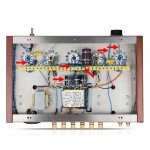
One last question. I have found another picture of this tube amplifier from a manufacturer, that sells it as a final product that's already built. He seems to have made some minor changes compared to the circuit schematic. I can see 1 additional 47uF cap parallel to the other 47uF cap. Two additional resistors at this place (One to decharge the caps ?? And the other one? )
And another two resistors, each directly between the input comming from the potentiometer and the pins 1 and 4 of the input tube.
Does anybody have an explanation for this?
Attachments
Resistors from potentiometer wiper to pins 1 and 4 are almost certainly grid stopper resistors.
Grid stoppers to reduce the chance of the parallel tube triode sections and the parasitics of the surrounding parts from become a Buttler oscillator.
I would guess the extra 47uF is one more stage of B+ filtering (perhaps the original 47uF to an added resistor to the added 47uF cap?
And the other resistor as a bleeder to discharge the filter caps, or part of a resistive divider?
Maybe the manufacturer has been reading all the suggestions on the various threads
about these kits.
Sorry, I have trouble looking at a photo, and then mentally 'creating' a schematic.
When I have an actual amplifier in front of me, and the 3D effect of seeing the real amp, I can better mentally 'create' a schematic, and sometimes
draw it out too.
Last edited:
PCL200,
Good catch! You found out my half truth statement.
No Quartz Crystal here.
I should have said a modified oscillator that is closest to a Buttler Oscillator.
All the unseen parasitics become the resonators.
Extra Credit . . .
Question:
What do you get when you cross an Armstrong Oscillator with a Colpitts Oscillator? . . .
An Armpits Oscillator.
Hopefully, for some that is a Tickler.
And for some others that have the dual capacity to divide the signal.
I am a glutten for Pun-ishment.
Last edited:
Extra Credit . . .
Question:
What do you get when you cross an Armstrong Oscillator with a Colpitts Oscillator? . . .
An Armpits Oscillator.
Hopefully, for some that is a Tickler.
And for some others that have the dual capacity to divide the signal.
I am a glutten for Pun-ishment.
No idea what this is about.
PCL200,
I am sorry, I should have left the puns out.
They only work for some, and not across different languages.
An Armstrong oscillator uses a Tickler winding for positive feedback.
Quite common with the old tube regenerative detector stages.
A Colpitts oscillator uses a capacitive divider (dual capacity) for the positive feedback.
Both the Armstrong oscillator and Colpitts oscillator are classic circuits (and not intended to be 'crossed' (not intended to be combined into one circuit).
- Home
- Amplifiers
- Tubes / Valves
- Nobsound EL34 DIY with left channel hum