It would seem most people build line-sources i.e. fairly narrow but tall ESL's.
How would it impact the performance if one were to bild something like a 39"x27" panel?
I assume it would improve the low frequency abilites and as long as the area is constant it shouldn't affect the SPL in a negative way.
However, the room reflections would be very different.
I suppose vertical dispersion would become an issue and listening standing up would be "not great".
So, hypothetically speaking... how would the sonic signature change depending on the shape of the panel?
Hi,
the dimensions affect basically two parameters.
1) the distribution character and
2) the acoustic impedance and phase cancellation
The first point is usually optimized for a broadend horizontal distribution and requires a small horizontal dimension
The second point is important for the onset frequency from which value phase cancellation occurs and how well or bad the diaphragm couples to the air. The larger the dimensions the better.
So You have to find a compromise.
Now it has been shown -either by Prof Hunt or Mr. Walker I don´t know at the moment- that a strip-like membrane shape with a height:width relationship of 8:1 works onto a real acoustic impedance not a complex any more over its full working frequency range. This is the ideal which for example the rather small danymic loudspeakers miss and why they need a box to beef up their response. A quadratically shaped membrane of same area would work onto a complex impedance hence the coupling to the air would be inferior and with lower efficiency.
So a strip shaped diaphragm with a ratio of 8.1 works to our favour in that it offers a rather small dimension horizontally and a good coupling to the air at the same. As a further postive sideffect the distribution character changes from a lobe to a cylinder with reduced early reflections from ceiling and ground and a more even SPL-distribution over distance.
And last not to forget...a thin tall strip looks much more sexy than a square shape
jauu
Calvin
Very interesting, the 8:1 ratio concept is new to me.
A 8:1 ratio will make for some very narrow panels. (Or some very tall ones)
I started writing some intricate questions but changed my mind.
In the end I think I can sum it up like this.
Is it worth it, building a "strip" shaped panel? Is it that much better? The low frequencies are likely to suffer?
Now it has been shown -either by Prof Hunt or Mr. Walker I don´t know at the moment- that a strip-like membrane shape with a height:width relationship of 8:1 works onto a real acoustic impedance not a complex any more over its full working frequency range. This is the ideal which for example the rather small danymic loudspeakers miss and why they need a box to beef up their response. A quadratically shaped membrane of same area would work onto a complex impedance hence the coupling to the air would be inferior and with lower efficiency.
So a strip shaped diaphragm with a ratio of 8.1 works to our favour in that it offers a rather small dimension horizontally and a good coupling to the air at the same. As a further postive sideffect the distribution character changes from a lobe to a cylinder with reduced early reflections from ceiling and ground and a more even SPL-distribution over distance.
And last not to forget...a thin tall strip looks much more sexy than a square shape
I agree that for the same radiating area tall and thin is always more pleasing to the eye than square.
Fortunately, it also tends to be more pleasing to the ear too with its better horizontal dispersion.
I would be very interested to know the source of the idea that an 8:1 ratio is the optimum.
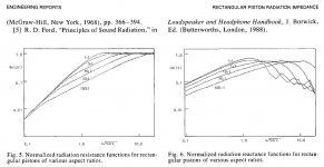
The real part of the radiation impedance does change more gradually with frequency for line sources than square source. But, I would think the optimum would be an infinitely long line source, not 8:1. See the first attachment for comparison of radiation impedance for different ratios of rectangular sources taken from AES.,Vol.38,No.5, 1990May "On the Acoustic Impedance of Baffled Strip Radiators" Note that impedance comparisons are for sources with the same area. So, for the same area a square radiator will be more efficient at radiating low frequencies than a line source in free space. At very low frequencies the efficiency for square and line sources converge.
But, our listening rooms are not free space.
If you can extend your line source floor to ceiling you will get the benefit of mirroring of the line source from the floor and ceiling. In practice, a floor to ceiling line source will have 3db - 6dB more efficiency at low frequencies(below 100Hz) than a square source of equal area. This may not be important for hybrids, but is a substantial advantage for a FR ESL.
So, as Calvin mentioned, line sources provide better horizontal dispersion and generally as good if not better efficiency at low frequencies.
PS
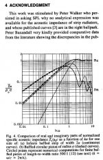
Looking at comparing radiation impedance for square and line sources with equal width instead of equal area, and the line source gains substantially in efficiency over the square source at frequencies below where phase cancellation begins. In fact, gaining 3dB for every octave lower in frequency. Such a comparison was published in AES Vol. 43, No. 7/8, 1995 July/August, "On the Acoustic Impedance of Baffled Strip Radiators". See 2nd attachment for this comparison.
Attachments
Last edited by a moderator:
Ok, line sources do seem to have some merits. Otoh Quad's are fairly square so you can probably get a good sounding speaker either way.
In my case, a floor to ceiling panel isn't an option so it'll be something like a 64" tall "strip" panel or a 28"x40" square panel.
Now, I'm perfectly happy with your explanations and the "strip" design is probably easier to build. The only reason I'm thinking about the square design as an option is because it would fit beautifully on top of dynamic bass. (Maybe a TH or a FLH?)
Quote:Otoh Quad's are fairly square so you can probably get a good sounding speaker either way.
Quads are rectangular in overall shape but they are a three way design using a narrow treble line source tweeter flanked by two wider mid range sections and two bass panel sections. They would not sound any good if they were a single full range panel of the same size.
Quads are rectangular in overall shape but they are a three way design using a narrow treble line source tweeter flanked by two wider mid range sections and two bass panel sections. They would not sound any good if they were a single full range panel of the same size.
Now it has been shown -either by Prof Hunt or Mr. Walker I don´t know at the moment- that a strip-like membrane shape with a height:width relationship of 8:1 works onto a real acoustic impedance not a complex any more over its full working frequency range.
I would be very interested to know the source of the idea that an 8:1 ratio is the optimum.
The real part of the radiation impedance does change more gradually with frequency for line sources than square source. But, I would think the optimum would be an infinitely long line source, not 8:1.
Calvin’s statement about a rectangular ESL with an 8:1 ratio having a real acoustic radiation impedance over its full working frequency range puzzled me greatly.
But, I think I stumbled on the source for Calvin’s statement. And, once the context of the statement is understood, it makes sense.
From "Telstar Shaped Electrostatic Speaker", by R. J. Matthys, Audio, vol. 48, May 1964:
“The diameter of a single electrostatic diaphragm (round or square) is about 1/24 of the wavelength of sound at the diaphragm’s resonant frequency. Since the air load on a diaphragm is reactive and not resistive when the diameter is less than one-third of the wavelength, a single electrostatic diaphragm will see a reactive air load in the frequency range between the fundamental diaphragm resonance and about eight times this resonant frequency.
Walker has shown that an electrostatic speaker reacts differently to a reactive load than does a moving coil loudspeaker…The best solution is to add speakers of the same size in parallel until the diameter of the speaker array is one-third the wavelength of sound at the fundamental resonant frequency of the diaphragm. This solution solves the reactive air load problem by making the air load resistive at all frequencies above the fundamental diaphragm resonance. Another way of accomplishing the same thing is to make the diaphragm rectangular, with the length of each diaphragm equal to eight times the width.”
Attachment (1) shows that for ka>1 (ie diameter > 1/3 wavelength) radiation impedance is resistive and constant.
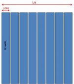
What Matthys said was that it would be possible to combine multiple smaller ESL panels into an array such that the resulting size would make the radiation impedance on each of the ESL panels resistive over their full working range even if this isn't the case when one panel is operated alone. If, as he states for his small ESL panels, the diameter is 1/24 wavelength at their fundamental resonance, an array of 64 panels arranged as in Attachment (2) would provide the desired resistive radiation over the full working range of the ESL panels.
Alternatively, Matthys states(highlighted in red above) that using rectangular shapes ESL strips with ratio of length to width of 8:1 could also be used to achieve the same result.
See Attachment (3).
Note that it is only the array of 8:1 ESL panels that achieves the resistive radiation over the full working range.
One 8:1 ESL panel operated by itself does not.
With just one 8:1 ESL panel, the radiation impedance turns reactive as soon as the wavelength gets longer than the width of the ESL panel, and you get a falling response with reducing frequency below this point. This is the dipole cancellation that we are all familiar with.
Attachments


Last edited:
Is there a practical way of calculating the diaphragm's resonant frequency?
If not it seems like a catch 22 situation to me?
You have to know the resonance frequeency to determine the width of the panels but you won't know the resonance frequency until you build a panel...
It seems a simple matter, resonance being a function of just two terms: diaphragm stiffness and airload mass.
But, there are a lot of inter-related items that impact these two terms.
1) Diaphragm stiffness is determined by:
- film thickness and the tension you apply to the film. This might be derived from heat shrinking, or stretching with weights or an inner-tube stretching table.
- the diaphragm bias voltage induces a negative stiffness term that subtracts from the mechanical stiffness of the tensioned diaphragm. It is mainly a function of bias voltage gradient in the gap and diaphragm area, but is also a weak function of the D/S spacing. Increasing bias voltage reduces stiffness and lowers resonance
2) The effective moving mass at resonance is determined by:
- the shape and size of the diaphragm. For the same area, a square has a larger airload than a rectangle
- any baffle extension added to the sides of the diaphragm adds to the mass and lowers resonance
- placing multiple panels next to each other increases the mass load and lowers resonance
With all these variables in play it is difficult to calculate in advance what the resonant frequency will be of an ESL in a final configuration. You can either follow a well trodden path and build panels with dimensions and film thickness used by others, or build a few test panels of your own to gather enough data to get you where you want to go.
That's pretty much what I was thinking.
Even if you could come up with a formula, the parameters would be near impossible to control in a diy situation.
Toying with numbers... a 70Hz resonance frequency would result in lambda being 4.91m.
Divide by three and we have a 1.63m wide speaker. I don't see this happening in many homes.
@115Hz we get a panel measuring a meter square. It looks like Hybrid is the way to go?
Toying with numbers... a 70Hz resonance frequency would result in lambda being 4.91m.
Divide by three and we have a 1.63m wide speaker. I don't see this happening in many homes.
@115Hz we get a panel measuring a meter square. It looks like Hybrid is the way to go?
For DIY, yes, hybrids certainly give you the best chance for success. If this is your first ESL build I would definitely recommend it.
One big advantage of hybrids is that the exact frequency of the fundamental resonance isn't important as long as it is an octave or so below crossover.
However, just to be clear, if you wanted to make an ESL that could cross at 70Hz to a subwoofer it doesn't necessarily have to be 1.5m wide. It only needs to be that wide if you want the radiation impedance to be resistive all the way to 70Hz for maximum efficiency. If you made it half that size, similar to a Quad ESL36, you could still achieve a flat response to 70Hz with a simple shelving network to compensate for the shifting of the radiation impedance from resistive to reactive.
Last edited:
Isn't this already put at work in many designs? Well, kind of?
It's common practise to insert spacers thus sectioning the diaphragm if one uses something like foam tape?
More numbers exercises...
Let's assume 1.1mm d/s spacing? Multiply that with 100 and we get 110mm spacer distance. multiply that by 8 and we get a total width of 880mm + spacer width. 12mm tape puts us at 988mm. Us a little wider tape at the edges and we're there, 1000mm.
Assuming we could adjust the diaphragm tension for 115Hz resonance frequency this would clearly be doable.
I don't know about the sonic properties but it works in theory?
Hi,
jauu
Calvin
This is imho not the case. The reason beeing that Mr. Matthys thinks of increasing the panel size means increasing the free vibrating distances at the same, hence reducing the resonance frequency, while with stacking multiple panels the resulting Fs remains nearly constant. While his thoughts are generally true regarding the lowerance of the Fs, they are off-practical, because if You don´t increase the d/s distance at the same the larger panel would become dynamically unstable. In other words, if You increase the panel size without increasing d/s distance You need to add spacers, which have the same effect as adding more panels. A as such mechanically segmented panel will show the same behaviour as a multiple of panels of segment-size. The single segmented panel though is easier to build, easier in handling and offers smarter optics.Note that it is only the array of 8:1 ESL panels that achieves the resistive radiation over the full working range.
jauu
Calvin
A mechanically segmented panel will show the same behaviour as a multiple of panels of segment-size. The single segmented panel though is easier to build, easier in handling and offers smarter optics.
I agree, no real difference between eight 8:1 ratio ESL panels mounted next to each other in a frame or a single square panel segmented into eight 8:1 ratio strips.
The point of the statement was that a single 8:1 ratio ESL panel by itself will not have a resistive radiation impedance to as low a frequency as eight of these panels mounted together. The radiation impedance for the single panel changes from resistive to reactive at a frequency 8 times higher than the array of eight panels(or segmented square panel if you prefer). As such the single 8:1 panel does not couple to the air at low frequencies as well as the large array.
There is nothing special about the 8:1 ratio for ESLs that provides a resistive radiation impedance over the full working frequency range as stated in post #2.
http://www.diyaudio.com/forums/planars-exotics/175067-no0b-esl-size-question.html#post2327152
Isn't this already put at work in many designs? Well, kind of?
It's common practise to insert spacers thus sectioning the diaphragm if one uses something like foam tape?
Absolutely. People build wide panels to delay the onset of dipole cancellation thus maximizing midrange - midbass efficiency.
But with width >> airgap size, spacers need to be added to insure static stability when the bias voltage is applied to the diaphragm.
Alternatively, some builders use silicone dots instead of full spacer strips to stabilize the diaphragm.
More numbers exercises...
Let's assume 1.1mm d/s spacing? Multiply that with 100 and we get 110mm spacer distance. multiply that by 8 and we get a total width of 880mm + spacer width. 12mm tape puts us at 988mm. Us a little wider tape at the edges and we're there, 1000mm.
Assuming we could adjust the diaphragm tension for 115Hz resonance frequency this would clearly be doable.
I don't know about the sonic properties but it works in theory?
Yes, you could choose a 1m x 1m size for your ESL panel to retain resistive radiation impedance down to ~115Hz and thus maximum efficiency down to ~115Hz. Then you could juggle diaphragm tension and number of vertical strip spacers to achieve whatever target resonant frequency you want. Remember, there is nothing special about the 8:1 ratio. It is the overall dimension of the panel that determines when radiation impedance switches from resistive to reactive.
The sonic properties...well it will be very very beamy in the high frequency range unless you find a way to segment to smaller areas with increasing frequency.
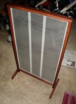
I just got done with my tweet/mid panels (see attached pic). The height:width ratio is 1.6:1 (32 inches high, 20 inches wide), much shorter and wider than most I've seen. I picked this for no reason other than that is essentially the golden ratio (0.618), and building them for tweet and mid which they seem to do beautifully.
The panel is segmented mechanically (3 vertical sections) but is electrically all one. The segmentation was done purely for mechanical reasons - to support the diapraghm so that it is not pulled into the stators. Didn't have any sonic considerations when doing this.
I don't think I will ever be going back to cone speakers.
Attachments
- Status
- This old topic is closed. If you want to reopen this topic, contact a moderator using the "Report Post" button.
- Home
- Loudspeakers
- Planars & Exotics
- No0b ESL size question