Hi,
I have a set of prebuilt pcb's that are suppose a preamp with balanced in and out 😕
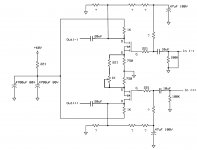
attached is the schematic I traced from the pcb. both FET's are IRFP240's
the output is connect to a 5k alps quad pot. measuring at the wiper, max
volume.
from this schematic, is it even possible to get balanced outputs that are + and - ?
I have a cheapy toy scope and cannot get the sinewave to stand still so
I cannot tell if it's really + and - or just both inverted outputs.
the output gain on the shorted (-) input to gnd is much lower. what is
the best way to balance the gain of the inputs?
my goal, single ended input on the Input +, Input - shorted to GND, balanced outputs + and -
Thanks for your help!
I have a set of prebuilt pcb's that are suppose a preamp with balanced in and out 😕
attached is the schematic I traced from the pcb. both FET's are IRFP240's
the output is connect to a 5k alps quad pot. measuring at the wiper, max
volume.
from this schematic, is it even possible to get balanced outputs that are + and - ?
I have a cheapy toy scope and cannot get the sinewave to stand still so
I cannot tell if it's really + and - or just both inverted outputs.
the output gain on the shorted (-) input to gnd is much lower. what is
the best way to balance the gain of the inputs?
my goal, single ended input on the Input +, Input - shorted to GND, balanced outputs + and -
Thanks for your help!
Attachments
If you redraw it as a regular old differential pair (LTP) maybe it will make more sense to you.
Being powered by a single rail, it would be similar to the Aleph P without current sources. The feedback/gate bias loop doesn't look right.
Being powered by a single rail, it would be similar to the Aleph P without current sources. The feedback/gate bias loop doesn't look right.
Thanks Alex/Bill
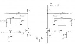
I redrew the circuit. it is for the most part a Bal.Zen.
I just need someway to balance the gains on the output.
Reduce the 750R source resistor on the Positive Input?
since that on has the much higher gain.
I triple checked the circuit and pretty sure this is how the pcb is laid out.
I redrew the circuit. it is for the most part a Bal.Zen.
I just need someway to balance the gains on the output.
Reduce the 750R source resistor on the Positive Input?
since that on has the much higher gain.
I triple checked the circuit and pretty sure this is how the pcb is laid out.
Attachments
I tried increasing the top source resistor from 750R to 1K.
Lower source resistor to 3.7K. It's always about 200mV difference between the + and - outputs.
should I be increasing the 1K on the top drain as well?
Lower source resistor to 3.7K. It's always about 200mV difference between the + and - outputs.
should I be increasing the 1K on the top drain as well?
The two schematics you posted are different in how the sources of the MOSFETs are connected. The first schematic is similar to that of Balanced Zen Pre (the sources are connected to each other with a pot in series with a small resistor, and separately to the ground with 750R resistors). The second drawing shows a different connection, with effectively different value source resistors for each MOSFET; this would result in different gains. Which one is the actual schematic of the board?
Hi Alex,
Bill pointed out earlier I did not draw the schematic right and he was correct.
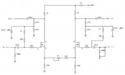
this is the final schematic and reflects what's one the pcb traces.
It's no good for single ended input and balanced outputs since both
outputs seem to be non-inverting, so I'm just using it as SE output.
It only has the positive supply.
Bill pointed out earlier I did not draw the schematic right and he was correct.
this is the final schematic and reflects what's one the pcb traces.
It's no good for single ended input and balanced outputs since both
outputs seem to be non-inverting, so I'm just using it as SE output.
It only has the positive supply.
Attachments
- Status
- Not open for further replies.
- Home
- Source & Line
- Analog Line Level
- No Name Pre