Simplicity of no-NFB pentode
A no--NFB pentode topology is straightforward and simple. Adding a global feedback loop to a SE circuit would be a difficult task due to loose coupling in output transformer. Local feedback, such as Schade, UL, or cathode, will in most cases require an additional amplification stage. Pentode output is so much easier than triode because there is no problem of Miller capacitance, and driver's swing requirement is typically 1/4 - 1/3 of what is needed for a triode. No slew rate problem, no need to run driver at tens of milliamperes.
Other than poor bass response with boxed speakers, I see no disadvantage in straight pentode topology, just benefits.
C-1550-inspired amplifier
Here is how I would modify the Philco amplifier if I were to build a flea-power SEP.

0.1 V sensitivity is not needed with modern sources, so I would use the low mu 56 instead of 57. The 56 will run at its best operating point and use audio choke as a load. The output tube would be the directly-heated 47 with grid choke and usual AC filament with hum-bucking pot. C2 and T2 leakage inductance form first order speaker crossover at the 47 output level. T1 can be wound on a small permalloy or amorphous toroid and optimized for its frequency range. Capacitor C1 and grid choke form high pass filter at 100-120 Hz to keep low frequencies out of the mid driver. If necessary, cathode bypass capacitor of 56 can be tweaked to make steeper LF cutoff. Low frequencies will be cared for by a separate powered subwoofer.
The 260 V power supply is to be capable of about 300 mA. Screen supply shared by two channels.
I bet this will rival any 45 SET.
Here is how I would modify the Philco amplifier if I were to build a flea-power SEP.
0.1 V sensitivity is not needed with modern sources, so I would use the low mu 56 instead of 57. The 56 will run at its best operating point and use audio choke as a load. The output tube would be the directly-heated 47 with grid choke and usual AC filament with hum-bucking pot. C2 and T2 leakage inductance form first order speaker crossover at the 47 output level. T1 can be wound on a small permalloy or amorphous toroid and optimized for its frequency range. Capacitor C1 and grid choke form high pass filter at 100-120 Hz to keep low frequencies out of the mid driver. If necessary, cathode bypass capacitor of 56 can be tweaked to make steeper LF cutoff. Low frequencies will be cared for by a separate powered subwoofer.
The 260 V power supply is to be capable of about 300 mA. Screen supply shared by two channels.
I bet this will rival any 45 SET.
Last edited:

A problem with AC filament is residual hum at 2x line frequency (120 Hz) that cannot be nulled with the hum-bucking pot. Whatever the source of this residual hum, it may be audible with high efficiency speakers like Magnavoxes or Philcos. The standard solution for this problem is Coleman regulator, but I don't like it because it involves noisy solid state rectification. FC may provide solution to this problem. The level of residual ripple in FC supply may be fine-tuned to cancel the 120 Hz filament hum. Otherwise, hum-bucking signal picked off power supply's smoothing choke can be fed into 47 grid or cathode circuit for cancellation. Steve Bench discussed the cancellation approach in much detail.
It is important to have clean, undistorted AC for filament, otherwise all line harmonics and noise will contaminate the signal. Line AC must be filtered, and filament supply transformer must have high primary inductance to operate away from saturation.
It is important to have clean, undistorted AC for filament, otherwise all line harmonics and noise will contaminate the signal. Line AC must be filtered, and filament supply transformer must have high primary inductance to operate away from saturation.
Your proposed 56/47 amp design appears to be optimized to use a maximum number of parts. And expense.
That will result in reduced reliability. And fewer $$$ to feed the builder!🙂
What are VR toobz doing in a circuit where they are not required?😱
SEP without some kind of NFB results in poor speaker damping,
A serious designer would not use 2.5V toobz when there are equivalent or better 6.3V toobz available.
And without the DH hum problem & need of a 2.5V winding on the PT.👎
A more than passable design with far less complication is easily possible with the toobz you have chosen.
But a SET circuit using a 45 will easily outperform this design on the basis of good DF of the speaker system.
But will need a driver with more gain than is possible with a 56.😀
Choke supplying the VR toobz will probably result in a good oscillator.
Better check that on the bench before building this Kopfschmerz. 😱
Better check that on the bench before building this Kopfschmerz. 😱
What are the three inductors in the driver circuit doing.? Looks to me they simply form a frequency dependent network.
But have nothing to do with obtaining a CC output to the lautsprecher.👎
But have nothing to do with obtaining a CC output to the lautsprecher.👎
Thanks for your input, jhstewart9. Where do you think the parts count could be reduced? I thought the scheme is as minimalistic as it could possibly be.Your proposed 56/47 amp design appears to be optimized to use a maximum number of parts. And expense.
That will result in reduced reliability. And fewer $$$ to feed the builder!🙂
Of course, VRs are dispensable, but tube data sheets list stable Ug2 as a condition for minimal pentode output stage distortion.What are VR toobz doing in a circuit where they are not required?😱
I think you kind of missed the previous discussion. This circuit is NOT to be used with conventional speakers that require electric damping. Moreover, the frequency range is purposely limited on the low side to avoid speaker's main resonance.SEP without some kind of NFB results in poor speaker damping,
Yes, one can use 6P5G and 6F6 instead, which would make things simpler and more conventional. But some people (myself included) believe that directly-heated tubes worth the trouble.A serious designer would not use 2.5V toobz when there are equivalent or better 6.3V toobz available.
That's why I am posting here - to learn from the community how things could be done better. Any suggestions are welcome.A more than passable design with far less complication is easily possible with the toobz you have chosen.
Again, you seem to miss the previous discussion. The whole thread is about no-NFB pentode approach to realize the benefits of speaker's current drive.But a SET circuit using a 45 will easily outperform this design on the basis of good DF of the speaker system.
But will need a driver with more gain than is possible with a 56.😀
If you really need current drive to the loudspeaker, why did you use fixed bias on the 47?🤔
An unbypassed cathode bias resister on the 47 would make a better current source.
An unbypassed cathode bias resister on the 47 would make a better current source.
That's right - this is not final, tested design. It is a proposal. If the thing oscillates, the choke can be substituted with a resistor. But I have done it before with no problems. Choke provides additional isolation from amplifier output and power supply. It is kind of luxury, not necessity.Choke supplying the VR toobz will probably result in a good oscillator.
Better check that on the bench before building this Kopfschmerz. 😱
You are exactly right: they form frequency- dependent network. It is a feature, not a bug. 56 plate choke, 47 grid choke, and coupling capacitor form high-pass filter to limit low frequencies to 100 - 120 Hz.What are the three inductors in the driver circuit doing.? Looks to me they simply form a frequency dependent network.
But have nothing to do with obtaining a CC output to the lautsprecher.👎
56 plate choke provides high impedance load so that gain is maximized. Gain is equal to tube's amplification factor. Plate choke allows effective use of plate supply voltage. With resistor in place of choke, Ua would be reduced by voltage drop in the resistor. 47 grid choke provides low resistance grid path, important for safe operation with fixed bias. These two chokes, because of their low DCR, make less thermal noise than resistors would make.
As a rule, cathode bias operation of a power pentode results in less power output and higher distortion. For Type 47, the difference between fixed and cathode bias is not very dramatic, but it is there. I prefer fixed bias because it always sounds better to my ears.If you really need current drive to the loudspeaker, why did you use fixed bias on the 47?🤔
An unbypassed cathode bias resister on the 47 would make a better current source.
Speaking of parts cost, there is nothing really fancy here, except maybe the autoformer volume control - if a really good one is desired. But there are cheaper versions of that.
Soundolier AT-10 line speaker volume control: $15-20. This is 11-step autoformer. Full winding inductance is about 45 H.
Hammond 154E choke: $20. It will need a relatively simple modification. The choke is rated 20 H at 20 mA. It needs to be opened and more winding added on top of existing one, about 3,000 turns of 40-42 AWG wire. There is enough window space for the additional winding, which should be wild and sectioned. Discard spacer when re-assembling the core. The sectioned portion of winding should be connected to 56 plate.
Russian teflon capacitors: we know how much they are. C2 must be K72 type, others could be FT2 or FT3.
47 grid choke: Midcom 8422 modem transformer. With two windings in series, inductance is 470 H. These transformers have 80% permalloy core. They are obsolete. They appear regularly on eBay as surplus. I bought in bulk paying less than dollar apiece.
Output transformer: nothing fancy here. It could be any small SE output transformer, the higher primary inductance, the better. No winding interleave or big core is necessary, as this transformer handles only mid frequencies. Spacing between primary and secondary is to be tweaked to obtain right leakage inductance for mid- high crossover. This is easy because in such transformers secondary is always on top of primary.
Core for high frequency transformer: about $30 at Mouser. Look for a Vakuumschmelze core with highest Al
Speakers are the most expensive parts. A Philco radio can be bought for less than $100, shipping included. Bohlender-Graebener Neo-8s is about $200 apiece, and all speaker outlets seem to be out of stock. But Aliexpress now have them at very competitive price. They list them as regular Neo-8, but according to their 8 Ohm impedance, they are Neo-8s.
The plate choke, grid choke, voltage regulator choke, and the low frequency single ended output transformer all have to pass DC.
That means they are all air gapped.
Well, the grid choke does not have significant DC current, so it does not need an air gap.
Air gapped chokes and transformers are quite sensitive to magnetic fields.
That means they can couple to each other, and can also pick up the fields from the non air gapped power transformer and the B+ air gapped filter choke.
Hum, hum, hum . . . unless you have lots of space between them, and have the proper angular orientation.
And, a magnetic steel chassis will couple all of those magnetic fields to all of the chokes and transformers.
Just my opinions
Last edited:
Other speakers can be used, but Philco/Neo-8s would be very hard to beat in this particular application. The Philco's sensitivity appears to be above 100 dB (need to measure), and Neo-8s matches it if crossed at 5-6 K.
Your opinion is right on the mark. Plate choke and grid choke should be magnetically screened, preferably with mu metal. The cheap way is steel wall outlet boxes from Home Depot. AT-10 is actially designed fot installation in such box. I hope it should be enough, as this is high signal level stuff, not sensitive preamp or phono stage, which would require more serious shielding.The plate choke, grid choke, voltage regulator choke, and the low frequency single ended output transformer all have to pass DC.
That means they are all air gapped.
Well, the grid choke does not have significant DC current, so it does not need an air gap.
Air gapped chokes and transformers are quite sensitive to magnetic fields.
That means they can couple to each other, and can also pick up the fields from the non air gapped power transformer and the B+ air gapped filter choke.
Hum, hum, hum . . . unless you have lots of space between them, and have the proper angular orientation.
And, a magnetic steel chassis will couple all of those magnetic fields to all of the chokes and transformers.
Just my opinions
Last edited:
'Sounds better' is a subjective observation. And in the Real World means little since others will never haveAs a rule, cathode bias operation of a power pentode results in less power output and higher distortion. For Type 47, the difference between fixed and cathode bias is not very dramatic, but it is there. I prefer fixed bias because it always sounds better to my ea'rs.
the same reproduction equipment as the observer. How often do we hear 'Sounds Better', but better than what?
Perhaps we are simply listening to which distortion 'Sounds Better' to our own ears.
To many including myself that kind of measure is less than meaningless.
I'm certainly aware of the objective of this thread as I watch a group of dreamers attempt to design an amplifier
for which there is no common speakers available.
Over many years I've built about 50 different amplifiers, both for personal use & for others. SE, PP, UL & on & on.
But never built an amp to be a current source intentionally. One early example of a current source
amp was a PP 6U6GT thing, I think I was about 15.
Other equipment designed & built included many analogue regulated power supplies, both constant voltage & constant current.
A common regulated PS is nothing more than a unipolar, NFB amplifier. The output is a replica of the reference source.
An ordinary amplifier can be reduced to a power Op Amp.
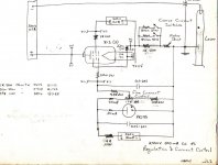
So here for your entertainment & wonderment is an example of a brute force constant current PS used to power an HE-NE laser.
The laser was hand built in the lab by grad student Eric Rawson on his way to a Ph.D in 1965. The PS requirement was not particularly
tight, on this project, just 1/2 Amp at 2.5 KV. I used 3x 813s as the passer's. And simply referenced to a VR tube. Schematic but no photo.
All the iron is special builds from Hammond. The whole thing was kinda heavy but it got the project running.
I did build several others of different capability for other projects.
All this in the same Lab at U of T where the first electron microscope in North America was built by a group headed by Prof EF Burton in 1938.
It was still there during the time I spent there, but not working. Burton & his grad students had all moved on.
Attachments
Fascinating stuff. You were lucky to be a part of this advanced research facility. I was a researcher myself before retirement, although in a different field.
Subjective vs. Objective in audio is an everlasting debate. I am sort of in the middle. If we could measure everything... Who said "if it measures good, but sounds not so good, you are measuring the wrong thing"?
BTW, I am not inventing a bicycle here. There were times when all speakers were high efficienvy and all amplifiers were no-NFB. Then Mrs. Vilchur, Thiele, Small, and Williamson turned the field in radically new direction, where it blissfully resides now. I just want to take a step back and see if there is anything amiss, almost irretrievably, in this brave new world.
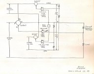
Here is another of considerably more complication. The load in this case is nominally 1/4 amp at 1500V, constant current.
The rectifiers are a full bridge of Si diodes on porcelain insulators & paralleled with Rs & Cs.
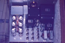
The passer consists of 6x 807s. The error amp has its own regulated 300V PS, completely independent of the main supply.
Another regulated 300V PS powers the 807 screens.
The main error amp references to an 85A2 gas regulator & samples the load current in a precision resistor.
All the iron is Hammond specials. But quite heavy, lots of iron. Off the top I don't recall which project this one went into.
It was almost 60 yrs ago. There were many constant voltage regulators for other projects as well.
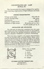
Another rather interesting application was to power a point source of white light to be used in photometric
& radiometric light experiments. Did that one with Ge transistors. The light source data is attached for any interested.
The lamp has a negative EI characteristic so must be operated from some kind of current limited PS. So used a CC regulator.
This lamp had to be started with something like a 2KV pulse. But once started it runs at only about 16V but several amps.
The HV starting pulse is locked out of the SS regulating circuit by series Si diodes.
As you can see I'm certainly familiar with circuits to get into current mode.
But I'm still not convinced that spending time on an amplifier such as in this thread is a worthwhile pursuit. 🙂
The rectifiers are a full bridge of Si diodes on porcelain insulators & paralleled with Rs & Cs.
The passer consists of 6x 807s. The error amp has its own regulated 300V PS, completely independent of the main supply.
Another regulated 300V PS powers the 807 screens.
The main error amp references to an 85A2 gas regulator & samples the load current in a precision resistor.
All the iron is Hammond specials. But quite heavy, lots of iron. Off the top I don't recall which project this one went into.
It was almost 60 yrs ago. There were many constant voltage regulators for other projects as well.
Another rather interesting application was to power a point source of white light to be used in photometric
& radiometric light experiments. Did that one with Ge transistors. The light source data is attached for any interested.
The lamp has a negative EI characteristic so must be operated from some kind of current limited PS. So used a CC regulator.
This lamp had to be started with something like a 2KV pulse. But once started it runs at only about 16V but several amps.
The HV starting pulse is locked out of the SS regulating circuit by series Si diodes.
As you can see I'm certainly familiar with circuits to get into current mode.
But I'm still not convinced that spending time on an amplifier such as in this thread is a worthwhile pursuit. 🙂
Attachments
A single ended air gapped output transformer can pick up the magnetic fields from the power transformer, and from the B+ choke.
This is especially true when . . .
1. There is no global negative feedback
2. The output tube is wired as a pentode or beam power tube. The plate impedance, rp, of those tubes often is between 15k and 25k.
Local negative feedback, such as Ultra Linear, Schade, output plate to driver cathode, and to some degree cathode feedback from the output transformer secondary to the output tube cathode - all will reduce the magnetic field hum pickup somewhat.
But a single ended triode, triode wired pentode, or triode wired beam power tube may have a plate impedance of less than 1k to 2.5k. That tends to swamp out the magnetic field from the power transformer or B+ choke (compared to the pentode or beam power tube).
Last edited:
What test equipment was used to provide this result? THXImpossible? Is the multitone measurements of intermodulation distortion adequate enough for you? For example, simultaneous 32 signals across the 20Hz-20kHz:
View attachment 1064580
- Home
- Amplifiers
- Tubes / Valves
- No-feedback pentode amplifier