Don't think so, if it were the center tap it should measure 115, but it doesn't. 135V+135V isn't equal to 230V. I think it's just induced voltage between the wires that it's reading.
I sounds to me like the earth pin does NOT go back to the center tap of the transformer. At least not in any low impedance path. If the pin were tied to ground, the measurements should not be 135 volts.
EDIT: Cross post with Daunestorey
EDIT: Cross post with Daunestorey
A safety ground can offer a a low impedance drain of noise into a "sink" which is the Earth. That can be helpful. But there are plenty of mains powered audio and video devices that have no connection to ground, and still work fine.
Safety ground is mostly there to quickly trip a breaker if a live wire comes into contact with a metal case. It protects you from being the conduit to earth, as the short circuit made from hot to ground will trip a breaker quickly. If it didn't then a metal case could be live, which would be dangerous if you touched it.
Safety ground is mostly there to quickly trip a breaker if a live wire comes into contact with a metal case. It protects you from being the conduit to earth, as the short circuit made from hot to ground will trip a breaker quickly. If it didn't then a metal case could be live, which would be dangerous if you touched it.
Measured how? To ground? To a nearby water pipe? To a ground at the other end of the building?...it boggles my mind though that there is a ground wire that isn't actually at 0V.
Asking because its not uncommon for grounds to be at other than 0v, at least by a little. Found one AC line ground that was at 50v from local earth. That one was a problem. Turned out it was caused by a faulty deep freezer at a neighbor's place, located a few houses down the road.

Of possible related interest:
Grounds for Grounding – Excerpts:
(IEEE Electromagnetic Compatibility Society, Sponsor)
2.7.3 Common-Mode (CM) to Differential-Mode (DM) Conversion |
Common-mode (CM) currents were previously shown to be generated from external sources unrelated to the circuit’s functional differential-mode (DM) currents. CM currents, however, could also be directly associated with signal currents. In balanced circuits, induced CM voltage will have little effect on performance. However, if CM current is converted into a DM signal, a differential interference across the circuit’s load will be introduced. Common-mode conversion is thus defined as the process by which DM interference is produced in a signal circuit by a CM signal. CM currents are converted to DM voltages through impedances Z1, Z2, Z3, Z4, ZS, and ZR, and capacitance C, shown in Figure 2.66 [18]. Common-mode currents existing in the circuit are converted into a differential mode voltage developed across the receiver port that constitutes of a summation of voltage drops resulting from various currents flowing through those impedances.

…
[Several Paragraphs Omitted]
...
3.1.3 Grounding-Related Myths, Misconceptions, and Misapprehensions
The term “ground” is thought to be a sort of cure-all concept, like fish oil, money, or motherhood and apple pie. However, whereas you can always trust your mother, you should never trust your ground. Many grounding anomalies and interference problems result from expectations of the ground system to perform inappropriate functions substantially beyond its capability
…
[Several Paragraphs Omitted]
...
Lessons Learned:
*There is nothing magical about “ground”; Ground is simply a path for flow of return current.
*The term “ground” is relative and is too ambiguous!
*To avoid confusion, avoid usage of the generic term “ground,” unless utilized in conjunction with some descriptive term or adjective.
*Ground is a very convenient fantasy invented by engineers to simplify life but, like other fantasies, does not exist in reality. Ground is not a current sink. Current flowing in a circuit must return (somehow) to its source. This seemingly fundamental concept is often overlooked, bringing about EMI problems.
*Myths, misconceptions, and misapprehension of grounding theory, units, and quantities are inherent in the integration of sensitive electronic equipment into a facility or platform. A common terminology for the concepts of power and frequency is mandatory for achieving a successful and effective design.
Grounds for Grounding – Excerpts:
(IEEE Electromagnetic Compatibility Society, Sponsor)
2.7.3 Common-Mode (CM) to Differential-Mode (DM) Conversion |
Common-mode (CM) currents were previously shown to be generated from external sources unrelated to the circuit’s functional differential-mode (DM) currents. CM currents, however, could also be directly associated with signal currents. In balanced circuits, induced CM voltage will have little effect on performance. However, if CM current is converted into a DM signal, a differential interference across the circuit’s load will be introduced. Common-mode conversion is thus defined as the process by which DM interference is produced in a signal circuit by a CM signal. CM currents are converted to DM voltages through impedances Z1, Z2, Z3, Z4, ZS, and ZR, and capacitance C, shown in Figure 2.66 [18]. Common-mode currents existing in the circuit are converted into a differential mode voltage developed across the receiver port that constitutes of a summation of voltage drops resulting from various currents flowing through those impedances.
…
[Several Paragraphs Omitted]
...
3.1.3 Grounding-Related Myths, Misconceptions, and Misapprehensions
The term “ground” is thought to be a sort of cure-all concept, like fish oil, money, or motherhood and apple pie. However, whereas you can always trust your mother, you should never trust your ground. Many grounding anomalies and interference problems result from expectations of the ground system to perform inappropriate functions substantially beyond its capability
…
[Several Paragraphs Omitted]
...
Lessons Learned:
*There is nothing magical about “ground”; Ground is simply a path for flow of return current.
*The term “ground” is relative and is too ambiguous!
*To avoid confusion, avoid usage of the generic term “ground,” unless utilized in conjunction with some descriptive term or adjective.
*Ground is a very convenient fantasy invented by engineers to simplify life but, like other fantasies, does not exist in reality. Ground is not a current sink. Current flowing in a circuit must return (somehow) to its source. This seemingly fundamental concept is often overlooked, bringing about EMI problems.
*Myths, misconceptions, and misapprehension of grounding theory, units, and quantities are inherent in the integration of sensitive electronic equipment into a facility or platform. A common terminology for the concepts of power and frequency is mandatory for achieving a successful and effective design.
It's been almost a year since this post, but I thought I'd post a reply anyway as it's something you could come across in some parts of Belgium and possibly elsewhere too.Well, the neutral is technically supposed to be grounded I think by the power company here. So the neutral should read 0V to ground and live to ground should be 230V. In my case you’re right I don’t really know which is which. But if I had a proper ground they would have shown a difference. At least in theory (in Spain you’re also supposed to assume both sides are live in case something is wired incorrectly).
The system you're on sounds to me like it's a 3x 230 V system and not a 230/400 V system. The giveaways are the voltages of 135 V between L and PE AND between N and PE.
The most common system in Europe is the 230/400 V system with N. This can be identified at a 230 V socket by measuring between the L and N prongs and PE. One will measure 230 V with respect to PE, in which case you've identified L. The other will measure 0 V with respect to PE in wich case it's N. This is assuming that there's no fault in the PE wiring. If there is, you would probably measure strange voltages higher than 0 V.
Phase voltage is 230 V (between L and N), line voltage is 400 V (between L1/L2/L3).
N and PE have a common connection to the earth. Several different earthing systems may be in use.
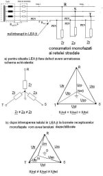
Now in this case there is 135 V between L and PE but also between N and PE. This 135 V immediately rang some bells with me as it's close to 230 V divided by the square root of 3 (and that's because of the phase difference of 120 degrees between each phase). This means that the DNO (district net operator) provides a 3-phase service without N. All sockets are wired between L1 and L2 and/or L1 and L3 and/or L2 and L3. PE is at earth potential, and since there's no N, the earthing system will most likely be TT as the other systems (TN, TNC, TNCS) all require a N conductor.
Phase voltage is 135 V, line voltage is 230 V.
The tricky bit is that in the house the same colours of wire might be used as in a 230/400 V system and this is also a reason why you must always treat BOTH L and N as live.
The distribution board in Belgium should have warning stickers telling you when you have a 3x 230 V service, but if you want to be absolutely sure which system you have, contact your DNO.
Last edited:
You're missing the point - the earth pin of my entire apartment is not connected to 0V. So nothing using an IEC pin will have a ground at 0V. That's the point of this post.
My question may seems stupid, but :
1 - Is there a real (officially built) ground point somewhere in your building ? If yes, it is usually located near the general cabinet (mains input) of your building, possibly in the basements.
2 - Your appartment has certainy an electrical cable tray or path of some sort to this general cabinet. Then : would it not be possible to route an earth cable to its ground point - assuming it exists ?
I do not say that it's easy nor doable, OK ?
But I could nonetheless do this - with the help of friends - years ago in my Parent's appartment, located at the 8th floor of a 1970 building, where the general cabinet was located in the basement, at the base of the electric cables main vertical path, distributing the 32 apparts of the tower.
It took us the whole day, but we succeded... 😎
T
Beware that this is an old thread, but I chose to reply as this closely resembles a service provided in some parts of Belgium (and possibly Spain) that seems to indicate a faulty circuit but is actually as it should be. Not all of Europe uses the 230/400 V system, and I found out the hard way.
As a result, this might have been the wrong conclusion:
In the 3x 230 V system, the only way to determine wether PE is actually connected to earth is to try and find metal pipework coming from the street and measure resistance between it and your PE. If this is low(ish), couple of Ohms, then you can be relatively sure it is earthed. The fact that duanestorey measured 135 V between both prongs and the PE prong leads me to believe that there is at least some connection somewhere low enough to give the multimeter a steady reference (but that does not necessarily mean it's low enough to be safe in case of a fault).
As a result, this might have been the wrong conclusion:
A standard socket tester would indeed indicate a missing PE as it's looking for a connection between N and PE, but in a 3x 230 V system, there is no N, only PE.You're missing the point - the earth pin of my entire apartment is not connected to 0V. So nothing using an IEC pin will have a ground at 0V. That's the point of this post.
In the 3x 230 V system, the only way to determine wether PE is actually connected to earth is to try and find metal pipework coming from the street and measure resistance between it and your PE. If this is low(ish), couple of Ohms, then you can be relatively sure it is earthed. The fact that duanestorey measured 135 V between both prongs and the PE prong leads me to believe that there is at least some connection somewhere low enough to give the multimeter a steady reference (but that does not necessarily mean it's low enough to be safe in case of a fault).
Last edited:
230/400 V:
For clarification, above image is of the 230/400 V system in which phase voltage is 230 V and line voltage is 400 V.
230 V sockets are wired between L1 or L2 or L3 and N (often on all phases to spread the load). 400 V operation needs only L1 and L2 and L3, N is not always used (e.g. motors don't need it). Sometimes N is used if a device also needs phase voltage and when loads are not spread evenly across the three phases. There are devices that run 400 V on just two phases, but threephase operation is preferred.
3x 230 V:
The 3x 230 V system must make do without a neutral conductor, the phase shift between L1, L2 and L3 creates the voltage difference necessary for current to flow, hence why sockets are wired between the phases. Line voltage is 230 V, but lacking N, there's no phase voltage. If there were, they would measure as 135 V w.r.t. earth potential, but this is not used.
Obviously, 400 V devices cannot operate in this system.
In both drawings, PE is left out for clarity but must be present, either as part of the service provided by the DNO (TN-systems) or a rod (TT-system).
A distribution transformer is normally wired with the phases connected in star configuration. This is not a centre tap but acts as a virtual grounding point, it is connected to earth to provide a current return path for fault currents. The grounding of this star point is why a fault current can flow through a person's body. There's a good reason why this is not left floating but that is beyond the scope of this post.
Below is an image of a typical circuit of the secondary windings of a distribution transformer in a 230/400 V system.
In this case the earthing system is TN-S. A TT-system does away with the PE conductor and an earth rod must be installed in the house near the distribution board. TN-C would combine N and PE in one conductor (aptly named PEN-conductor).
In a 3x 230 V system, only the three phases may be provided by the DNO in which case TT earthing must be used.
Last edited:
Land of innovation, the land of the rising sun - Japan: ''TT'' system with RCD  !!! Just implement it, and please implement it fast! Everything else TN-C, TN-CS, TN-S etc. is history and potential problems. Oops, yeah..... you need permission. Ok, we'll sit and wait - the bright futures.
!!! Just implement it, and please implement it fast! Everything else TN-C, TN-CS, TN-S etc. is history and potential problems. Oops, yeah..... you need permission. Ok, we'll sit and wait - the bright futures.One advantage of a TN-system is that its upkeep is the responsibility of the DNO whereas the earth rod at the consumer's house in a TT system is not. It's the home owner's responsibility. It may be rotting away unnoticed for years creating a high PE to earth impedance. In that scenario a live to earth fault would result in unsafe voltages of the PE conductor and everything connected to it. Hopefully the RCD hasn't failed too. Reality is it too may have failed years ago (who on earth tests these things as per the instructions...every month???, I know I don't and I should know better).
I have seen 50VAC on an earth ground on a 120/208VAC system. It wasn't caused by any rot in the power system. It was caused by a faulty food freezer in a house down the street on the same distribution transformer. The earth grounds at the distribution transformer and the grounds at the panels of all the houses on that transformer did not have a low enough impedance to ground to pull the fault voltage to lower than 50VAC. If the earth is dry where the ground rod is placed, such things can happen.
If the ground pin is not connected to anything and you have somewhere a piece of equipment with a RFI filter at the mains input, then it will have capacitors between L-ground and N-ground forming a capacitive voltage divider. So you will measure equal voltages between both if you just slap on a voltmeter between ground and L or N.
As said above, "ground" and "earth" are concepts for engineering and used as references. But do not assume they are a miracle 0V (AC or DC).
As said above, "ground" and "earth" are concepts for engineering and used as references. But do not assume they are a miracle 0V (AC or DC).
Yes, agreed, but in this case the measured 135 V between L and PE and N and PE was the exact same value I measured at a client's house near the historic centre of Mechelen. It was then that I found out about the 3x 230 V system in use there.
That's what prompted me to write about this type of service as it's not actually that common in Europe and can easily lead to false assumptions.
A capacitive divider would halve the measured voltage to 2 x 115 V, if both capacitors are equal, so that doesn't seem to be the case here. If they're not equal, then voltages are not equal but cannot be higher than 230 V when added.
Last edited:
TT with RCD is not better or safer than TN-S. TT cannot be reliably used in locations where soil resistivity is high.Land of innovation, the land of the rising sun - Japan: ''TT'' system with RCD
An RCD would still function in an installation without any earthing.
Regardless of the earthing system in use, the impedance is what determines safety. The lower, the better. In that respect, a TT system may indeed not always be the best option.
Regardless of the earthing system in use, the impedance is what determines safety. The lower, the better. In that respect, a TT system may indeed not always be the best option.
#36, #37 Wow boys, are you serious? So let's face it, we all get distracted in class sometimes but......give yourself another chance - think again🙂. Your DNO..... And yes, Markw4 /#33, #39/ is right.
- Home
- Amplifiers
- Power Supplies
- No earth connection? How does it affect audio?