Hi all,
I have tried to simulate a PSU based on transformer /Bridge Rectifier/ Capacitance Multiplier combination.
Although the simulation 'plots' OK there are no DC operating points (circuit probe) using transient analysis - all zero.
Using the DC operating point simulation I get the same result - all values zero.
The transformer was designed using the topics on LT and various other web sites but I'm thinking this might be the problem area as using ± power supplies with a sine wave input works fine on analogue circuits.
All the Spice simulator settings are 'default' as far as I know.
Any ideas?
TIA
Attachments
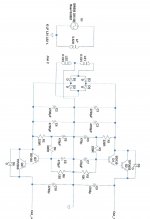
Capacitance Multiplier? That looks like a typical unregulated power supply with a slightly delayed power up (C5 & C7).
± As per the ESP pages (similar to JLH design).Capacitance Multiplier? That looks like a typical unregulated power supply with a slightly delayed power up (C5 & C7).
If R5 and R6 were zener diodes, I can see some form of use otherwise I can see no practical advantage as any ripple that is present, on C3 and C4, has no where to go due to almost zero voltage drop across Q2 and Q4.
Its normal not to see dc voltages in a simulation like that because there are no DC sources present to calculate an initial operating point. The simulation is dynamic and must be probed to see the voltages.
Its normal not to see dc voltages in a simulation like that because there are no DC sources present to calculate an initial operating point. The simulation is dynamic and must be probed to see the voltages.
Thanks for your reply, Mooly.
Probing with the simulators probe during transient analysis gives no voltages, current or obviously dissipation figures - if that's what you mean.
Otherwise I have to revert to using pure DC voltage sources? I guess I could 'graph' these results as 'graphing' (plotting) does work with the circuit as depicted.
Thanks Mooly,
Yeh I guess it's the transformer simulation that's the problem. Plotting works OK but not the simulator probe.
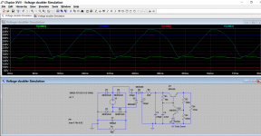
Attached is a screen shot (printer is giving up-hill - sorry) of the simulation for completeness. Shows the final output voltages and the voltage across the input cap banks.
The 2 'dummy resistors' (R7/R8) are there to give a current of around 1.6 Amps for the simulation.
Cheers
Yeh I guess it's the transformer simulation that's the problem. Plotting works OK but not the simulator probe.
Attached is a screen shot (printer is giving up-hill - sorry) of the simulation for completeness. Shows the final output voltages and the voltage across the input cap banks.
The 2 'dummy resistors' (R7/R8) are there to give a current of around 1.6 Amps for the simulation.
Cheers
Attachments
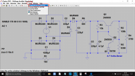
Printer !
Goto 'tools' and 'copy bitmap image'. Then just paste into Paint etc. Or use the sniping tool in Windows.
I thought I'd seen that facility somewhere 😱
Thanks.
- Status
- Not open for further replies.
- Home
- Design & Build
- Software Tools
- No DC Operating Points