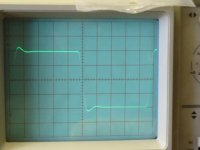
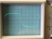
Tiny bit of overshoot but otherwise looks good.
And the sound ?
Anyway, inserting a 100R in the output is always a smart move, just in case you get a short at the output (easy with RCAs), to avoid smoking the JFETs... it will also protect against oscillations.
If you use it to drive headphones (but the JFETs seem a bit wimpy for that) you must add a resistor since headphone jacks short for a brief time on connection.
Hi Peufeu,
i don't know how it sound because i take all mesurement on my breadboard. thank you Maxpou
i don't know how it sound because i take all mesurement on my breadboard. thank you Maxpou
Hi maxpou,
Pulse response looks good, no ringing at all, try some small compensation capacitor over local feedback resistors to take care of overshoot.
Pulse response looks good, no ringing at all, try some small compensation capacitor over local feedback resistors to take care of overshoot.
Hi Maxou,
You could as well try without the output followers. The overshoot will most probably vanish, the stability (into capacitive loads) is amazing. I would probe the output while it is connected to the following amp and check the sound both with complimentary output follower and without.
Nice work, keep it going!
Rüdiger
At what freq?
Rüdiger
Edit:
if it's 10kHz, it's not good. I have a very simple version of this with 170/74 in the front and BC550/BC560 as VAS, set for 6dB of gain, and the square is fine up to several tens of khz!
Rüdiger
Edit:
if it's 10kHz, it's not good. I have a very simple version of this with 170/74 in the front and BC550/BC560 as VAS, set for 6dB of gain, and the square is fine up to several tens of khz!
Hi Maxpou,
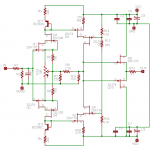
you could swap the bases of Q14 and Q18 to the corresponding FET drains. increases (ol-) gain and decreases distortion.
Rüdiger
you could swap the bases of Q14 and Q18 to the corresponding FET drains. increases (ol-) gain and decreases distortion.
Rüdiger
maxpou said:
Hi Maxpou,
in my opinion
please f*** 2nd, 3rd, 4th harmonics
but beware of this 15kHz peak!
Better use OLG,
true
Onvinyl said:Hi Maxpou,
you could swap the bases of Q14 and Q18 to the corresponding FET drains. increases (ol-) gain and decreases distortion.
Rüdiger
Hi Rüdiger,
i use the schematic in post #5 not the schematic in post 7.
padamiecki said:
Hi Maxpou,
in my opinion
please f*** 2nd, 3rd, 4th harmonics
but beware of this 15kHz peak!
Better use OLG,
true
Hi padamiecki,
i don't understand your all message, but yes i will test OLG with local feedback later.
Thank you! Maxpou
- Status
- Not open for further replies.
- Home
- Amplifiers
- Solid State
- no current mirror, current mirror, cascoded current mirror, bjt or jfet VAS?