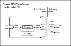
Great clarification, as always. Yes, an Ohm or two in series with the low-voltage winding might be important because the impedance might get terribly low at some point or other (which might or might not influence the frequency response).
Which leads back to an inconclusive earlier discussion: what, who, and where is ground and/or chassis? What are the ground references for the transformer frame or input wires, etc?
It seems to me, with high voltages around, circuits need to be anchored a bit. One method (from Mike Wright) is to have 2200 Ohm half-watt resistors from each side of the amp to ground (or is that chassis?). And some point of the HV supply ought to be grounded (or chassied?).
With 2200 Ohms connected to a part, there is no leak of power but any stray high voltage will be leaked close to ground potential.
Ben
Last edited:
See what happens when the OP(me) asks a question, with the wrong understanding, and you give the correct answers on the assumption that he does understand. Ha! I'm a retired tech from ATT and there were oodles and oodles of times when trans and receives circuits were always getting crossed because of misunderstandings: types of equipment, manufactures, where you were in the circuit, etc. Frustrating but also funny sometimes. Ben, Bolserst, and Jer, I'm gaining a little more understanding from your great posts. I sure wish I had those ST70 OPT primary and secondary schematics from Bolserst when I started!
I changed the bias return to the red lead CT with the 10 meg resistor. Still works fine. However before when I'd turn the bias off while playing music, the sound would still play for a while. Now it dies immediately. Does that matter?
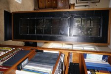
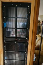
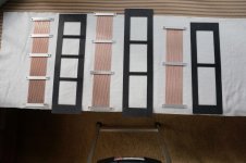
Below is a picture of one the wire stats. The frames are from two old Magnepan MGII's that a guy from work was throwing out. Having problems with resonances, so need to tinker.
Bond
I changed the bias return to the red lead CT with the 10 meg resistor. Still works fine. However before when I'd turn the bias off while playing music, the sound would still play for a while. Now it dies immediately. Does that matter?
Below is a picture of one the wire stats. The frames are from two old Magnepan MGII's that a guy from work was throwing out. Having problems with resonances, so need to tinker.
Bond
Attachments
It is normal for the to keep playing even after the bias supply has been shut.
My best set of panels ( the ones that I sadly burned up) used to still play the next day with only a slight loss of efficiency due to its construction of very high resistance to diaphragm charge leakage.
You can try adding some dampening to curb your low frequency resonance issues.
Some have used some sort of Felt or a fine mesh of silk screen can be used as well.
There have been many such discussions on this subject.
http://www.diyaudio.com/forums/plan...licon-dots-resonance-control.html#post1954189
https://www.google.com/search?q=ESL...KEwiMo6Tgz43IAhXIWj4KHVzcDjo&biw=1280&bih=855
https://www.google.com/search?q=esl...KEwjp1pnb0Y3IAhULfpIKHQq_BP4&biw=1280&bih=855
jer 🙂
Last edited:
No it does not matter. But…why is it happening you ask?… I changed the bias return to the red lead CT with the 10 meg resistor. Still works fine. However before when I'd turn the bias off while playing music, the sound would still play for a while. Now it dies immediately. Does that matter?
The F40 HV module has an internal bleeder resistor to discharge the power supply when the input voltage is removed. It is likely in the 10Meg – 20Meg range. So, when you turn off the power supply the panel will be discharged fairly quickly thru the circuit formed by your 10Meg series resistors and the internal bleeder resistor. Note that many of the EMCO modules do not have internal bleeder resistors.
If I am looking at your picture from post#17 correctly, you previously had the HV module connected to the 4 ohm tap(brown wire). In that case, the only way your panel was charging up was thru leakage resistance between the primary and secondary windings….many 100s of Megs. So, when you turned off the power supply, this large resistance was in the discharge path so it takes a while to discharge the panel. You likely noticed it took longer to charge up to full output as well.
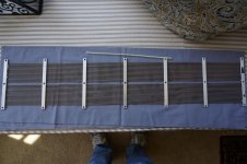
Very nice looking panels 🙂Below is a picture of one the wire stats. The frames are from two old Magnepan MGII's that a guy from work was throwing out. Having problems with resonances, so need to tinker.
As geraldfryjr already mentioned, adding some acoustic damping will help with resonance problems.
A single layer of thin crafting felt(1/16 inch) on the rear stator provides about the right amount for most cases.
This thread provides some measurements with and without crafting felt on an Audiostatic ESL.
Without acoustic damping:
http://www.diyaudio.com/forums/plan...diostatic-baffle-step-filter.html#post3345523
With single layer of damping felt:
http://www.diyaudio.com/forums/plan...ostatic-baffle-step-filter-5.html#post3491306
Last edited:
damned again such a nice looking wire stator, do you have a few pictures of the construction ? what rig you used ?
Geraldfryjr: Thanks for the links. My wife has lots of different materials stored throughout the house, but silkscreen is not one of them. Will have to go looking. Maybe try some felt too.
Bolserst: Yep, I originally had the bias return on the brown lead thinking it was one of the available 'secondary' taps. Doesn't seem to have caused any harm, fortunately.
Your description of how my panels fired up and decayed is very accurate. My concern was that they died immediately, and that good panels should keep a charge for days(well not quite that long) after shut down. Good to know how the F40 works. Jeepers, you have a wealth of information!
Thanks for the nice comment on the panels.
Wrinex: Thank you too for your comment.
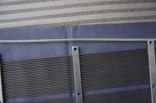
The only jigs I used were for making the aluminum support bars for the wire stators; glass templates for the other parts. Two sheets of glass were used: one where you draw the position of your wire supports with their holes using a black sharpie, making sure they're square and aligned, and then turning the glass over so the sharpie side is on the bottom, but you can still see your template through the glass. This way the lines don't get smeared and you can clean the glass when needed. A white sheet of paper underneath helps with contrast. Thicker glass also helps with flatness. You then align the wire stators on the template using a few of the nylon edging grommets(see picture below) and then taping the stators to the glass with masking tape. Using a slow setting epoxy(10 -15 minutes), you glue the aluminum supports to the stators and then carefully laying the other sheet of glass on top, weighted down with something like a can of paint or a couple of big cans of tomato sauce will do.
The panels themselves are made out of 1/16" ABS sheet plastic. It's very easy to work with. You just score it with a utility knife and break your piece off. It also comes in 3/32 and 1/8 inches thicknesses. The edging grommets work perfectly with 1/16" RG45 welding rods. They are bendable so in theory you could construct a curved wire stator with them. Below also is a picture of a smaller stator I built a while ago. The center hole was probably not needed since they're not that wide. If you think you'd like to try building one this way, I suggest tinkering with a small size at first. Any questions, please let me know.
Bondsan
Bolserst: Yep, I originally had the bias return on the brown lead thinking it was one of the available 'secondary' taps. Doesn't seem to have caused any harm, fortunately.
Your description of how my panels fired up and decayed is very accurate. My concern was that they died immediately, and that good panels should keep a charge for days(well not quite that long) after shut down. Good to know how the F40 works. Jeepers, you have a wealth of information!
Thanks for the nice comment on the panels.
Wrinex: Thank you too for your comment.
The only jigs I used were for making the aluminum support bars for the wire stators; glass templates for the other parts. Two sheets of glass were used: one where you draw the position of your wire supports with their holes using a black sharpie, making sure they're square and aligned, and then turning the glass over so the sharpie side is on the bottom, but you can still see your template through the glass. This way the lines don't get smeared and you can clean the glass when needed. A white sheet of paper underneath helps with contrast. Thicker glass also helps with flatness. You then align the wire stators on the template using a few of the nylon edging grommets(see picture below) and then taping the stators to the glass with masking tape. Using a slow setting epoxy(10 -15 minutes), you glue the aluminum supports to the stators and then carefully laying the other sheet of glass on top, weighted down with something like a can of paint or a couple of big cans of tomato sauce will do.
The panels themselves are made out of 1/16" ABS sheet plastic. It's very easy to work with. You just score it with a utility knife and break your piece off. It also comes in 3/32 and 1/8 inches thicknesses. The edging grommets work perfectly with 1/16" RG45 welding rods. They are bendable so in theory you could construct a curved wire stator with them. Below also is a picture of a smaller stator I built a while ago. The center hole was probably not needed since they're not that wide. If you think you'd like to try building one this way, I suggest tinkering with a small size at first. Any questions, please let me know.
Bondsan
Yes, odd for sound output to decay so fast. Might be worth exploring. Generally, there are 20 megOhms in all directions from a panel as well as uncountable megOhms across the diaphragm.My concern was that they died immediately, and that good panels should keep a charge for days(well not quite that long) after shut down. Good to know how the F40 works. Jeepers, you have a wealth of information!
Following unplugging my ENCO(s), very slow loss for hours. After far as safety, my guess is there no stored energy to speak of within a minute of the EMCO being unplugged. But sound should still be strong from the panels.
Ben
I just had my mom pick me up some sheer type window curtain material last time she was at Joann Fabrics, I think it is like 100 to 120 thread count.
There are some photos of it in one of these threads. 🙂
jer 🙂
P.S. Here they are !!!...... And another small discussion on Dampening. 😉
http://www.diyaudio.com/forums/plan...ut-segmented-wire-stator-esl.html#post4184639
There are some photos of it in one of these threads. 🙂
jer 🙂
P.S. Here they are !!!...... And another small discussion on Dampening. 😉
http://www.diyaudio.com/forums/plan...ut-segmented-wire-stator-esl.html#post4184639
Last edited:
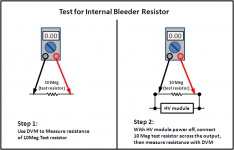
If I recall correctly, your EMCO module is of the dual polarity variety. If so, it does not have internal bleeder resistor according the the Tech Rep I received info from. if you have a DVM capable of measured resistances in the Mohm range, you can measure it for yourself. I'd recommend first measuring a test resistor in the 10Mohm range to make sure your meter is measuring as expected. Then connect the test resistor across the output leads you are using from the HV module...with power off of course. Then measure resistance of the test resistor again. If your module doesn't have an internal bleeder resistor the test resistor will measure the same as in step 1. If it measures lower, there is a bleeder resistor and you can calculate it from the two measurements using the formula for parallel resistances.Following unplugging my ENCO(s), very slow loss for hours. After far as safety, my guess is there no stored energy to speak of within a minute of the EMCO being unplugged. But sound should still be strong from the panels.
In case you would like to experience what a bleeder resistor does during the discharge cycle you can hook up an external one as shown in the 2nd attachment. Usually you set the value to draw about 5% - 10% of rated current.
BTW, all this talk of bleeder resistors is really only relevant for HV supplies like the EMCO that can supply considerable current (2.5mA in the case of the F40 module). The usual HV multiplier circuit typically used for ESL bias supplies have so little current capability that bleeder resistors would need to be in the 100s of Gohm to keep from dragging down the voltage during normal operation.
Very fortunate indeed since at HV turn on when the panel has not attained full charge, most of the HV would be across the primary and secondary windings. Then again, most transformers are designed to handle 2kV - 3kV between windings for isolation safety reasons. The bigger concern is driving transformer with two large an audio voltage which can exceed the layer to layer capability within the same winding which often doesn't have insulation between them.... Yep, I originally had the bias return on the brown lead thinking it was one of the available 'secondary' taps. Doesn't seem to have caused any harm, fortunately.
Attachments
Last edited:
I've been playing with these things for a several months now so thought I'd update how things turned out and maybe vent a few frustrations.
As mentioned before there were some resonances, especially in the bass region...mostly due to panel vibrations from the old Magnepan frames. Basically my bass consisted of one note-the resonance of the wooden frame. I tightened things up and added 2x2's in the back to stiffen the panel. That helped quite a bit.
Secondly, the left speaker never was as loud, and the loudness would vary. With no music playing there occasionally was a thumping sound coming from the diaphragm....arcing that took me a long frustrating time to find. One of the nylon screws holding the stators to the ABS frame had pushed a minute piece of copper tape from the stator too close to the diaphragm. Since it was covered by the screw you could not see the arc, even in the darkness. Jeepers.
The panels started sounding better but still not what I was hoping for. After about a month I gave up on them, putting them back in the garage and going back to listening to my Klipschorns(nothing wrong with that). Now these are not the first ESL's I've built. I had some small panels up in the attic that I built about twenty years ago, so brought them down and fired them up, burnt holes and all. Now this is what I remembered...clarity, smoothness, and holographic imaging, on a small scale though.
So started tinkering with the "newer" panels. I broke the cells from one 5x11" to two 5x5" by adding a one inch spacer in the center. By doing this the bias voltage could be increased from 2kv up to around 2.7kv, with less arcing, even at quite loud levels. Also the imaging has improved. Maybe the diaphragms have loosened up too, since there seems to be more resolution and I'm hearing the decay of the music much better...something the Khorns excel at. They now bring a smile to my face. Of course I still have the same problem that most ESL's have...I need a tennis ball hanging by a string from the ceiling to guide where my nose needs to be for optimum imaging.
Still tinkering, but have also started a new project. Something similar to the varying cell size panel of a Sound Lab ESL. Below are some updated pictures. Thanks again to all for the great help and guidance. Will be picking your amazing brains again soon.
Bondsan
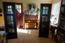
Tried again.
jees did i miss something stunning panels ! they look incredible slik straight and nice! i am gone scroll back to see if you have any photo's of making these. they look beautifully!
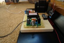
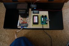
btw thats an expensive bias supply ......
![ST-70composite1600[1].jpg](/community/data/attachments/475/475216-e254a6069cb0c7769feadbecdc310c29.jpg?hash=4lSmBpywx3)
![DynacoMarkIIIschematic[1].jpg](/community/data/attachments/475/475230-3667df1b75011cc07d529b538d83ef22.jpg?hash=NmffG3UBHM)
- Status
- Not open for further replies.
- Home
- Loudspeakers
- Planars & Exotics
- No CT on Transformer for Bias return