Hello all,
I am trying to use two output transformers from an old Dynaco ST70 for my step up voltages on my ESL's. The problem is they do not have a CT for my bias supply return that seems to be required on most schematics. I've read where some people say you can use any available secondary tap with the proper xmeg resistor or connect to the amp's chassis ground with a proper xmeg.
I was also wondering if I could just use any tap from a separate isolated transformer, output or power, as the bias return. Or, would it be possible to use the other panel diaphragm as the return and reverse the stator polarity. Any of the above? Lots of questions!
I will be using an EMCO F40 for my bias supply, and while it was not terribly expensive($55,Ebay), I'd rather not be throwing it in the 'oops' bin right off. Any suggestions or ideas are greatly appreciated. Thanks a bunch.
I am trying to use two output transformers from an old Dynaco ST70 for my step up
voltages on my ESL's. The problem is they do not have a CT for my bias supply return
Can you post the schematic?
Here the schematic from Mark Rehorst's website. I'm using an F series EMCO module instead of the G series.
ESL Bias Supply Construction
ESL Bias Supply Construction
I am trying to use two output transformers from an old Dynaco ST70 for my step up voltages on my ESL's. The problem is they do not have a CT for my bias supply return that seems to be required on most schematics. I've read where some people say you can use any available secondary tap with the proper xmeg resistor or connect to the amp's chassis ground with a proper xmeg.
You could connect any one of the available secondary taps to the CT connection of your HV supply thru a 10Meg resistor and it would operate just fine. You do not have to use a secondary tap that is perfectly centered for the panel to charge up and operate properly. Also, you do not necessarily have to have a connection to the amp chassis ground.
Alternatively, the virtual center-tap approach used by Acoustat in their MK-141 interface works great.
See attached schematic and simplified layout.
Attachments

Last edited:
bolserst,
Thanks for the info. Need to get to the parts store for the resistors, but hopefully will have the panels fired up by the weekend. My wife is not exactly thrilled with having these things in the living room, especially since there is already a pair of Klipschorns residing, but she is very understanding.
Thanks for the info. Need to get to the parts store for the resistors, but hopefully will have the panels fired up by the weekend. My wife is not exactly thrilled with having these things in the living room, especially since there is already a pair of Klipschorns residing, but she is very understanding.
No Center tap is actually needed in some case providing the Winding's DC resistance is low enough to not cause an imbalance.
When using OPT's be careful to not use a very high bias voltage as most aren't designed to sustain such high voltages that ESL's require.
Many including Myself have burned out a perfectly good working pair of OPT's because of this.
jer 🙂
When using OPT's be careful to not use a very high bias voltage as most aren't designed to sustain such high voltages that ESL's require.
Many including Myself have burned out a perfectly good working pair of OPT's because of this.
jer 🙂
Geraldfryjr,
How much is too much bias voltage for the OPT's? I think I'll be in the 2-3kv range. Will that be safe? Thanks for the caution.
How much is too much bias voltage for the OPT's? I think I'll be in the 2-3kv range. Will that be safe? Thanks for the caution.
As long as you include 10Megohm or higher resistance in series with the HV supply you can't damage the transformer since there won't be any significant voltage drop across the winding resistance. 2-3kV sounds perfectly reasonable for a panel with diaphragm to stator spacing of about 1/16".How much is too much bias voltage for the OPT's? I think I'll be in the 2-3kv range.
Be aware that geraldfryjr likes to push the limits in his DIY ESLs. When he is talking about "very" high voltage, he is talking about running the bias voltage high enough to cause the air in the gap to ionize. If your stator insulation isn't perfect and you aren't using high enough value series resistors, the panel can arc resulting in very high voltage across the transformer winding which can certainly burn them up.
Yes!!!...... Very Very Good point Bolserst !!! 🙂
I would consider not going more than 2-3kv as mentioned, I think it is safe to say that most OPT's might be constructed to handle up to 1.5Kv to 2.5Kv.
But if one were using your typical ESL schematic you may find voltages as high as 5Kv or so and this can be a bit to high for some transformers.
Failure of stator coatings is the biggest problem and can/will cause a winding to burn an instantly open or short should it fail.
If you are using a smaller power amp (50 to 100 watts) then you should be okay.
But I have had an Antek AS-1206 fail on me using my Crown DC300 and it was only producing 4Kv-4.5KV p-p at its output as those are rated at a Static test of 3500v between the windings.
Luckily I was able to repair the burned section of the Antek and never had a problem with it after that, and I was able to continue testing the core at such voltages.
That testing I did with the Antek was done with no panel connected and the failure was completely at the fault of the transformer itself.
jer 🙂
Last edited:
...But I have had an Antek AS-1206 fail on me using my Crown DC300 and it was only producing 4Kv-4.5KV p-p at its output as those are rated at a Static test of 3500v between the windings.
The failure you describe was due to audio voltage(AC) stepped up by the transformer to well above the secondary winding rated capability. Your words of caution to not overdrive the transformer with too big of an amplifier is certainly valid. However, Bondsan isn't asking about that. Rather, he is asking about the bias voltage level which is the low current DC high voltage(2-3kV) used to force charge onto the diaphragm. It will not cause transformers to fail even at 10kV as long as 10Megohm or larger series resistors are in place. All of the voltage will show up across the resistor or air gap, not the low resistance of the winding.
Yes, I can concur with that.
In fact the least amount of danger to windings is when both the secondary and and primary are at the same potential , IE Ground.
This way the only voltage difference that is present between the winding's is due to the amplifiers input voltage minus the stepped up output voltage going to the stator's.
We had a thread on this earlier.
Not this one but some of it is mentioned here,
http://www.diyaudio.com/forums/plan...ting-better-output-esl-panel.html#post2873939
Here it is!!
http://www.diyaudio.com/forums/planars-exotics/205136-ground-reference-esls.html#post2874876
Not to be OT but what I was trying to state was the signal coming out the transformer in my test was 4-4.5KV Peak to Peak.
This equates to only a Peak voltage of half that at 2-2.5Kv at any one instant with reference to ground.
2.5Kv is well under the Antek transformers rating of 3.5Kv and it should not have blown.
Only one winding was damaged and it was the top most winding of the stack of two 115v winding's,
Also it only occurred when I hooked up the electrostatic shield to the ground reference point of my test jig.
This indicates a slightly poor amount of insulation between the top 115v winding and the aluminium tape electrostatic shield that was between it and the two LV (6v) winding's.
And it was proven as such when I tore the thing down to see if I could repair it.
Sorry for going of topic but I felt a little explanation was needed in order to understand what had actually happened in that test.
Yes, I have ran as High as 12KV to 14Kv of bias on my ESL's with no damage to the transformers or amplifiers driving them, Ever!!!
Providing that the core and/or the two winding's (Pri. & Sec.) are all referenced at the same ground potential and this actually includes the stator's relationship to ground in the circuit as well, See Figures A&B&D below.
Except of course my poor little cheesy 6V6 pp OPT's back in 2003 probably mostly from over driving them as it was my very first setup.
But I did enjoy them for many months before that fateful day. 😉
First one went and then later the other, and yes I was starting push the bias quite high back then as well. 😉
I may have very well not properly grounded them as I was just a newbie at it back then with lots yet to learn, and the hard way I might add!! He,he,he,he 🙂
jer 🙂
Attachments

Last edited:
Gerald ever had the time to so something with the stators i send you ?. complete of topic btw.. but i think the answer was given already by bolsert 🙂
nice simple idea about the center tap, i always went for double transformer to solve this. but this is way cheaper🙂 (if you manage to get same stepup ratio)
nice simple idea about the center tap, i always went for double transformer to solve this. but this is way cheaper🙂 (if you manage to get same stepup ratio)
WrineX, I haven't had a chance yet been pretty busy, sorry for the delay.
I am planing a build thread to feature all three construction techniques I have done on building Desktop ESL's and those are by using Window Screen, TIG Rod and PCB material.
I need to get going on it since I haven't heard any music on anything decent in the last 2 1/2 years now.
I want get on it soon so I can at least get the painting done outside before the extreme cold sets in.
I have still been concentrating on PICchip MCU's and programming to get the ESL preamp control center and amp and interface done before I get the HV stuff back out again.
Once that is finally done and I make the three sets I will finally start on a DD amp for them as well that has been on the back burner for quite some time.
Cheers !!!
Carry on with the topic. 🙂
jer 🙂
Hi Bolserst,
Thanks for the reasurance and your explanations. I may want to return the Dyna OPT's someday to their original intent and rebuild the amp. It's good to know that they will likely survive this project.
The local parts store did not have any HV 10 or 20 meg resistors, so I'm waiting for them through the mail. Maybe sometime next week I can try these things out.
How can an output transformer not have a centre tap on the tube side?
But.... I rather like the Acoustat virtual supply posted by Bolserst because you have large protective resistors in all directions.
While on eBay, you might locate an astonishing deal on a lab power supply on a board for like $15. It does what the Rehorst variable supply does and it has a digital read-out. Buy a spare because they sometimes break when you fool with them.
Ben
In the days before REW and testing, I used a pair of Dynaco ST70 transformers. Seemed pretty good... but then all ESLs are pretty good. Now I'm waiting till they're worth $1000 on eBay.
Ben
Ben
Hello Ben,
Thanks for the reply. Actually I did use a built LM317 power supply module from Amazon for around $12. It does have the digital voltage readouts, which is handy, and it seems to work very well with the EMCO. For people like me who have a very limited knowledge of electronics, it's a simple way to construct a bias power supply.
Maybe the Dyna OPT's have a CT on the primary side, since there are five taps, but the info I read seemed to specify it on the secondary side. I'm afraid I'm ignorant on how trans work, besides stepping up and stepping down voltages. Any knowledge or advice I can get from all of you extremely experienced electronic wizards and DIY's is most appreciated. The main thing is that with the 20 meg resistor on an available secondary tap for the bias return, it seems to be working just fine.
I'll try to post some pictures when I can figure out how. Right now I get a message that I'm missing a security token.
Listening wise, the speakers sound pretty good, but definitely need some tweaking. Not as smooth as I was expecting, but also a lot more dynamic than I thought they'd be. This is from person who has Klipschorns. Will post some more impressions later.
Attachments

For more info on learning about the Step-up Transformer and how it relates to an ESL check out these threads.
There are many more great ones but this is one of the best places to start.
It is a very in depth study and at times may be a bit confusing as I was learning as I was going as well.
http://www.diyaudio.com/forums/planars-exotics/161485-step-up-transformer-design.html#post2088330
And these as well,
http://www.diyaudio.com/forums/planars-exotics/246137-esl-transformer-question.html#post3709981
http://www.diyaudio.com/forums/plan...p-up-measurements-part-1-2-a.html#post2823635
http://www.diyaudio.com/forums/plan...idal-transformers-esl-panels.html#post3656396
Congratulations on getting your ESL's running!!
I am sure that you will enjoy them for everything that are meant to be!!! 🙂
Cheers!!! 😀
jer 🙂
Last edited:
While I love to see folks experimenting, I'd be careful near high voltages!!!Maybe the Dyna OPT's have a CT on the primary side, since there are five taps, but the info I read seemed to specify it on the secondary side. I'm afraid I'm ignorant on how trans work, besides stepping up and stepping down voltages. Any knowledge or advice I can get from all of you extremely experienced electronic wizards and DIY's is most appreciated. The main thing is that with the 20 meg resistor on an available secondary tap for the bias return, it seems to be working just fine.
Yup, that's the module. Your work is very sanitary.
Confusing which is primary and which is secondary here since ESL have 'em reverse of tube amps. Tube-amp primary for ultra-linear transformers should have 5 leads and secondary should have 4 (grd, 4 ohms, etc).
Ben
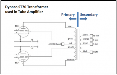
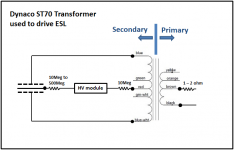
In general terms, the input to a transformer is called the primary and the output the secondary. Confusion arises when you use a transformer for a purpose other than that intended by the designer. In the case of using a push-pull output transformer to drive ESLs, the input and output swap sides since you desire to step voltage up not down. I know in several other threads we had started using the terms LV(Low Voltage) and HV(High Voltage) when talking about transformers driving ESLs to avoid the primary/secondary confusion.
In any case,…
Attachment #1 shows how your Dynaco transformer would be used in a push-pull output stage.
Attachment #2 shows recommended circuit for driving ESL with your Dynaco transformer.
Originally I thought you were saying that the CT (ie red wire) was missing so you needed an alternative way to hook up the bias circuit. But bentoronto’s astute observations have uncovered that that is not necessarily the case. You can connect the HV supply to the CT(red wire), or either of the screen taps(green or green-white wire) thru the 10Meg resistor and you should not notice any difference in output level or quality. When connecting to the CT the 10Meg resistor isn’t necessarily needed, but it adds a level of protection for your transformers from the HV supply. Personally, I would keep it in the circuit.
If you want to avoid any chance of damaging your transformers, I would recommend connecting the amplifier to the 4 ohm connection as shown(ie between black and brown wires) with amplifiers up to 100Watts. If you are using a smaller amplifier (30Watts or less) you could increase the output by +4.5dB connecting between the orange and yellow wires. For even more output (+7.5dB) connection of amplifier to the brown and orange wires could be used, but avoid amplifiers with outputs > 20Watts.
In all likelihood, the transformers will handle higher amplifier power than those I mentioned above, but at least you know where the "grey line” starts. Whether you choose to step over it is up to you. I have used similarly sized Stromberg Carlson transformers with the orange-yellow wire connection with 150W amplifiers for 5+ years without any issues. But, that doesn’t guarantee your transformers will hold up.
Attachments
- Status
- Not open for further replies.
- Home
- Loudspeakers
- Planars & Exotics
- No CT on Transformer for Bias return