Hi all hifi specialists
Following burned output transistors 2SB817 and 2SD1047 and cannot get original ones, i have soldered new ones 2SC2581 and 2SA1106. The problem is that I cannot adjust the bias VR and I got .04 mV only. I have verified all soldering which are ok. I get a rather good sound on my speakers I can say a better bass, but I do not want to risk playing at higher volume.
Grateful have your advice for a solution.
Regards
Alain from Mauritius.
The order in which you detail the original transistors is
2SB817 (PNP) 2SD1047 (NPN)
comparing that for the replacements the order of type is reversed
2SC2581 (NPN) 2SA1106 (PNP)
One has to ask if you installed the replacements with like types NPN for NPN and PNP for PNP.
Sorry did not reply to your post #19 as getting confused with TR swapping..too many testing.
The order of NPN/PNP is reversed in earlier post but have checked on the board PNP and NPN are soldered in the right place.
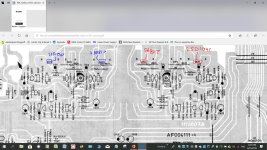
Now may be the following can be of help to you..ive measured some voltages on main TRs
The order of NPN/PNP is reversed in earlier post but have checked on the board PNP and NPN are soldered in the right place.
Now may be the following can be of help to you..ive measured some voltages on main TRs
An externally hosted image should be here but it was not working when we last tested it.
Sorry for earlier link. This one gives you a better picture of the voltages on the main transistors. Also could you explain to me how to include a pic in the post itself instead of having to send you to a link. Tks
Extract Rotel RA931 voltages — imgbb.com
Extract Rotel RA931 voltages — imgbb.com
Q613 is always saturated at 0.6V , you don´t have available adjustment because either R619 or VR601 or a track joining them is open.
To confirm, with amp OFF, measure resistance between Q613 Base and Emitter on the 20k *resistance* scale, not the diode scale.
You "should" have 2k2 + whatever the bias trimmer is set to but I guess you´ll find the chain is broken somewhere.
Another possibility is that Q613 is shorted Base to Collector, so you now have the BE diode dropping fixed 0.6V
When power stage dies, it often kills the bias transistor, one way or another, or simply the dirty bias trimmer is open (poor wioer contact).
In any case it should be replaced as a safety measure.
EDIT: just found your edited schematic wiith measurements: it confirms it´s one of my 2 hypothesis: you have fixed 0.6Vce on Q613, all other voltages are "normal" considering what Q613 drops.
Last edited:
Since the problem is still unsolved, please *do* the measuring and post results.
Yes, but since one of the OP´s answers was:^ Post #3 mentions the fault transferring to the other channel when the output transistors are swapped L to R.
and yourgetting confused with TR swapping..too many testing.
The order of NPN/PNP is reversed in earlier post
was NOT answered, I ask for precise measurements and tests instead.Can you just confirm again (no need to actually do it again, just to be sure I understand correctly) that when you swapped the output transistors between the channels, that the fault moved with the output transistors ?
Last edited:
The order in which you detail the original transistors is
2SB817 (PNP) 2SD1047 (NPN)
comparing that for the replacements the order of type is reversed
2SC2581 (NPN) 2SA1106 (PNP)
One has to ask if you installed the replacements with like types NPN for NPN and PNP for PNP.
Having looked at the service manual I note the pcb board layout for the two channels are mirror images of one another - a point I hope you noted with regard to the above.
In case there is any confusion I have made some notes on the schematic to identify how the output transistors should line up.
Attachments
Sorry to all. let me correct the following error as I myself got confused when describing the swapping operation in earlier post.
In fact after swapping the original transistors pair 2sd1047 2sb817 from right to the left channel , the situation remained unchanged on L channel i.e no bias adjustment was possible.
On the R channel with the swapped pair 2sc2581 and 2sa1106, I had no problem with bias adjustment.
So to conclude there is no issue with the right channel. After the above tests all output transistors have been resoldered back in their original places. Apologies for wrong info in the earlier post.
Now to reply to mjona, I confirm the placement of the transistors as per schematics i.e 2sc2581 npn on external left side and 2sa1106 middle left side.
Resistance measurement at Q613 between b and e goes from 2k2 to 4k18 ohms progressively when I turn the VR fully towards one direction.Q613 is always saturated at 0.6V , you don´t have available adjustment because either R619 or VR601 or a track joining them is open.
To confirm, with amp OFF, measure resistance between Q613 Base and Emitter on the 20k *resistance* scale, not the diode scale.
You "should" have 2k2 + whatever the bias trimmer is set to but I guess you´ll find the chain is broken somewhere.
Another possibility is that Q613 is shorted Base to Collector, so you now have the BE diode dropping fixed 0.6V
When power stage dies, it often kills the bias transistor, one way or another, or simply the dirty bias trimmer is open (poor wioer contact).
In any case it should be replaced as a safety measure.
EDIT: just found your edited schematic wiith measurements: it confirms it´s one of my 2 hypothesis: you have fixed 0.6Vce on Q613, all other voltages are "normal" considering what Q613 drops.
ATTN ALL
Good news and thanks to all.
I proceeded as follows:
I have tested all medium and output transistors. All were ok.
I have removed also the VR and the surrounding resistors and checked them on DMM.
They were all OK. So I cleaned the surroundings on the board with alcohol.
The lint was soiled with some dirt. ( The weather around being most of the time very humid in the tropics) and and All components were soldered back and there was the miracle.
The bias on the VR was right back and adjustable. Bulb test OK. Music OK and slightly more musical with the replacement TRs 2SC2581 and 2SA1106.
I have measured the DC offset as follows:-
DIRECT SPEAKERS REMOTE SPEAKERS
Left Right Left Right
-1.0mV -8.0mV 35.5mV 37.3mV
So I appreciate your advice and any possible solution please. Thank you.
ALAIN

Have a look at LittleDiode – Electronic Components for All they have the original transistors listed.
I got an irfp9240 from littlediode and it lasted 10 minutes until I unplugged my soldering iron and it blew up.
So I bought a new one from RS Components and not for lack of trying I cant blow it up. I can only guess they were copy/fake parts. They cant have been very sure because they refunded me without question.
I have seen a couple of threads about fake parts from Littlediode.
I would go for different genuine parts than risk fake parts that blow up if you fart near them. You might have to change bias circuit a little but that's probably just one resistor.
There isn't really a single path through the power amp. It behaves as a 'whole' although there are easily identifiable 'building blocks' making up the power amp such as the LTP or long tailed pair input stage. There are constant current sources such as Q603 and Q607/609. There is the voltage amplifier stage (Q611) and the driver and output stages.
You can't just 'pick up the signal' within most of that, and at some points (such as the input to the voltage amplifier) the signal is unrecognisable.
Its really a vast subject that you need to study if you are interested by reading lots of books.
You can't just 'pick up the signal' within most of that, and at some points (such as the input to the voltage amplifier) the signal is unrecognisable.
Its really a vast subject that you need to study if you are interested
by reading lots of books.- Status
- This old topic is closed. If you want to reopen this topic, contact a moderator using the "Report Post" button.
- Home
- Amplifiers
- Solid State
- No bias voltage on Rotel 931 following change of output transistors