Do you know what is the NJM4556 output impedance when it is used like a buffer?
Inverting input connected to the output.
Gain = 1
Regards.
Alfredo Mendiola Loyola
Lima, Peru
Inverting input connected to the output.
Gain = 1
Regards.
Alfredo Mendiola Loyola
Lima, Peru
Its essentially zero, but remember there are finite limits on what it can drive due to its limited current delivery.
probably ~1 uH - at a guess the open loop output Z is going to be less than the ~100 Ohms seen in lower current output op amps of the same semi process era - I'll call it ~50 Ohms lacking datasheet info to the contrary
then just divide by feedback excess loop gain at the frequency you are looking at
GBW is advertised as 8 MHz, open loop gain 100 dB typ
probably accurate to within a factor of 2 up or down
then just divide by feedback excess loop gain at the frequency you are looking at
GBW is advertised as 8 MHz, open loop gain 100 dB typ
probably accurate to within a factor of 2 up or down
Do you know what is the NJM4556 output impedance when it is used like a buffer?
Inverting input connected to the output.
Gain = 1
Regards.
Alfredo Mendiola Loyola
Lima, Peru
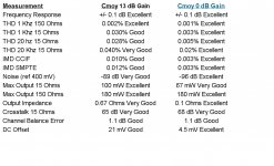
Its 0.1 Ohms as per NwAvGuy: Cmoy With Gain
Attachments
As jcx says, the output impedance of a buffer is an inductance not a resistance.
If I may split some hairs: the output impedance rises with frequency due to decreasing loop gain.
Therefor, it looks like an inductor.
But you knew that of course.😉
Jan
I said it is an inductance (impedance effect), not an inductor (physical component). It does, of course, look very like an inductor as it not only has the rising impedance with frequency but also the 90 degree phase shift.
That is why putting some capacitance at a buffer output can create problems: the L and the C form a tuned circuit. At the very least you can get ringing; at worst you get oscillation if there is any extra phase shift.
That is why putting some capacitance at a buffer output can create problems: the L and the C form a tuned circuit. At the very least you can get ringing; at worst you get oscillation if there is any extra phase shift.
So the external series resistor that is often used, like 50 ohms, is just there to kill the Q of the tank?
Jan
Jan
I think it's a bit more subtle than that Jan. If you do a loop gain plot and then add some capacitance, what you see is poles that lie above the ULGF and therefore with gains of <1 migrate down in frequency so that they lie below the ULGF and with gains >1. Then, the system is unstable, or nearly unstable.
The output resistor, or inductor in a power amp, prevents the pole from migrating downwards for normal capacitive loads - the problem of capacitive loading is then solved.
Similar mechanisms BTW on 3 terminal regulators with low ESR output caps - the solution there is to use a high(er) ESR cap which inserts a zero in the load.
As is often the case in engineering, there is more than one way of viewing what happens when you add a resistor to a buffer output. You could view it as damping Q, or swamping negative resistance, or shifting poles.
- Status
- Not open for further replies.
- Home
- Amplifiers
- Headphone Systems
- NJM4556 Output Impedance