Have anyone done ribbon by ferromagnetic material like iron, nickel, cobalt or compounds like invar etc?
Pros:
1) Stronger magnetic field than in air gap has.
2) Linear magnetic field.
3) Even ceramic magnets will do. No need for neodyms.
4) Ribbon can be wide and both magnetic flux and linearity can still be excelent.
5) Magnets can be placed many ways to avoid cavity resonance in "air gap".
Cons:
1) Ferromagnetic materials have bigger density and resistivity than aluminum. However bigger magnetic flux compensates that a bit especially in big and wide ribbons.
2) Magnets attract ribbon so that ribbon should propably be mounted at sides too without resonances at used frequency range and that is the BIG problem.
In my opinion iron alloys have too much corrosive problems, cobalt is dirt expensive. Pure nickel seems to be the best if anyone like to test this.
I found that thin nickel foil down to 8um is commercially available. One manufacturer:
Special metals
Any comments?")
Pros:
1) Stronger magnetic field than in air gap has.
2) Linear magnetic field.
3) Even ceramic magnets will do. No need for neodyms.
4) Ribbon can be wide and both magnetic flux and linearity can still be excelent.
5) Magnets can be placed many ways to avoid cavity resonance in "air gap".
Cons:
1) Ferromagnetic materials have bigger density and resistivity than aluminum. However bigger magnetic flux compensates that a bit especially in big and wide ribbons.
2) Magnets attract ribbon so that ribbon should propably be mounted at sides too without resonances at used frequency range and that is the BIG problem.
In my opinion iron alloys have too much corrosive problems, cobalt is dirt expensive. Pure nickel seems to be the best if anyone like to test this.
I found that thin nickel foil down to 8um is commercially available. One manufacturer:
Special metals
Any comments?
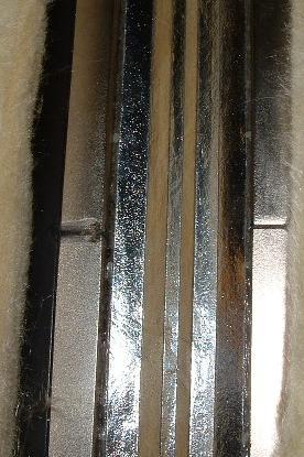
This is a mesuerment of a 30mm wide ribbon whit iron powder on the back side.
An externally hosted image should be here but it was not working when we last tested it.
I wanted the ribbon to get pulled by the magnets.The i ribbon i made is glued the neomagnets.
The main ting is not that you get and increased sensivity but it goes much higer 50 kilo maybe.
The "invention" was made by Johnny Sorensen.And printed i a danish magasin called Highfidelity some 15 years ago.
The main ting is not that you get and increased sensivity but it goes much higer 50 kilo maybe.
The "invention" was made by Johnny Sorensen.And printed i a danish magasin called Highfidelity some 15 years ago.
Interesting
So you attach both long sides of a ribbon to magnets? Or just one side and let the iron powder and magnets keep the ribbon straight?
Both are good ways to avoid twisting of the ribbon or making wrinkles by misuse. This construction is very strong and stable. Something that I have also tried to do because long full range ribbons are too sensitive for all kind of air movements in a room.
But how does the ribbon move then? It should stretch. There comes few problems I haven´t solve yet:
1) This stretching acts like a spring which try to avoid ribbon movement. It makes a resonant frequency depending on ribbon mass and it´s tensile stiffness. How to construct ribbon so that this frequency is not in band? Especially when having a full range ribbon?
2) Because of stretching, ribbon excursion and SPL are limited and poor?
3) Also ribbon like this bend. Sides doesn´t move but the center does. It makes a kind of cone resonances that should be dambed somehow at joints. How?
Both sides are glued.I have corrigated et the other way like this.Then it can move.
An externally hosted image should be here but it was not working when we last tested it.
Correction....
2) Ribbon excursion and SPL are limited ONLY IF resonance frequency due tensile stiffness and mass is in band or above.
I doubt that you can make this resonance below, let´s say 200Hz with glued full range ribbon working down to 200-300Hz. Not at least if excursion compared to ribbon width is significant when tensile force increase more than linear as a function of ribbon excursion. Then even 1mm excursion can be too much.
Let´s put it another way... Glued ribbons work but they propably have a lot of resonances and THD and so free ribbon advantages have been lost except line source behaviour.
If you know how these disadvantages can be avoided, I am now extremely interested of your project !!! Especially if ferromagnetic ribbons like nickel or iron powder can be used.
2) Ribbon excursion and SPL are limited ONLY IF resonance frequency due tensile stiffness and mass is in band or above.
I doubt that you can make this resonance below, let´s say 200Hz with glued full range ribbon working down to 200-300Hz. Not at least if excursion compared to ribbon width is significant when tensile force increase more than linear as a function of ribbon excursion. Then even 1mm excursion can be too much.
Let´s put it another way... Glued ribbons work but they propably have a lot of resonances and THD and so free ribbon advantages have been lost except line source behaviour.
If you know how these disadvantages can be avoided, I am now extremely interested of your project !!!
Especially if ferromagnetic ribbons like nickel or iron powder can be used.This is a measurement of my ribbon.This one does not got iron pouder, but it you can see it can go below 300 hz.It is 20mm wide and 150cm long
An externally hosted image should be here but it was not working when we last tested it.
It seem that resonance frequency is not a problem there. Great work!
How have you corrugated your ribbon so that ...
1) ... foil doesn´t ring.
2) ... it stretch enough?
Have you measured what is the maximum excursion at lowest used frequency? And is there a lot of THD when played loud?
How have you corrugated your ribbon so that ...
1) ... foil doesn´t ring.
2) ... it stretch enough?
Have you measured what is the maximum excursion at lowest used frequency? And is there a lot of THD when played loud?
1. yes and becorse the way the magneticfield put the force on the ribbon
2.yes and it gets very stif'
1 meter long
2.yes and it gets very stif'
1 meter long
An externally hosted image should be here but it was not working when we last tested it.
Wonder about the sensitivity compared to an aluminum conductor in the same set up??
The ribbon equation shows that you are fighting conductivity and mass, thus the usual approach is aluminum due to reasonable conductivity and low mass.
I'm unclear on the benefit of using nickel conductors and their magnetic properties in your construction? Could you explain that?
Regards,
_-_-bear
The ribbon equation shows that you are fighting conductivity and mass, thus the usual approach is aluminum due to reasonable conductivity and low mass.
I'm unclear on the benefit of using nickel conductors and their magnetic properties in your construction? Could you explain that?
Regards,
_-_-bear
bear said:
The ribbon equation shows that you are fighting conductivity and mass, thus the usual approach is aluminum due to reasonable conductivity and low mass.
I'm unclear on the benefit of using nickel conductors and their magnetic properties in your construction? Could you explain that?
I don´t know if nickel ribbon has any benefits in reality. That´why I asked if anyone have ever tried the idea
I do agree that since nickel has bigger density and resistivity, if has 1/10 of sensitivity compared to aluminum foil in the same magnetic field.But...
...by using nickel ribbon you should be able to have very high magnetic flux density through the whole ribbon no mather how wide the ribbon is. Sound good when building "full range" ribbons that are wide and have big area.
With a nickel ribbon the flux is mostly limited by the saturation flux density of nickel and that is almost 2 Tesla. So nickel ribbon sensitivity compares to aluminum one with ABSOLUTE UNIFORM 0.2T flux density through whole air gap no mather, how much the ribbon moves. Everybody knows that a field in a air gap is never fully uniform.
So with a nickel ribbon you propably suffer a bit with sensitivity but get much more linearity and therefore less THD.
And there is also another benefit. It is the cost.
With a nickel ribbon you need to have flux only in the ~10um ribbon where all the current flows instead of the whole, let´s say, 10mm deep air gap.
And with nickel the flux follows the ribbon even if it moves centimeters !!! So total flux is really small and ceramic magnets should work fine if flux is focused by small pieces of ferromagnetic rods to the sides of the ribbon. No need for expensive neodyms nor iron loop behind the ribbon to get enough field.
I would test this if only had nickel foil !!!
One more benefit...
With a aluminum ribbon you need to build the air gap very deep in order to get linear magnetic field. This cause cavity resonance and nonlinear frequency response.
With a nickel ribbon you can connect the ribbon sides to very sharp ferromagnetic rods that focus magnetic flux into the ribbon and use vertically corrugated ribbons. This construction has practically no air gap depth and therefore no cavity resonance !!!
You can get it even thiner from her.
http://www.goodfellow.com/csp/active/gfHome.csp
http://www.goodfellow.com/csp/active/gfHome.csp
ABJensen said:You can get it even thiner from her.
http://www.goodfellow.com/csp/active/gfHome.csp
Even 0.025mm thick and 300mm wide 99% aluminum foil costs 114 euros a meter or 183 euros 10 meter there. Hey come on... that is normal cooking foil !!!
Dirt expensive

I made an interesting FEMM simulation.
What if we have long ribbon 200 x 2 cm and rotate magnetic flux and current 90 degree? So magnetic field is vertical and current horizontal
With a nickel ribbon you can do it !!!
Magnetic flux flows the whole 200 cm from up to down in the nickel ribbon and is looped back in an iron rod. There is only one relative small magnet in the loop somewhere. Can be neodym or ferrite. Total loop length is about 4 m but the single magned is enough since in the ribbon the area is really small. Only 2 cm x 10 um.
Imagine: You need only one cheap magnet !!! Total magnetic flux is only about 1/100 than needed with traditional ribbon. Sounds cheap. You cannot do that with an air gap. With a ferromagnetic ribbon you can.
But then again... current should be the same ~100 times larger if same sensitivity is needed. How to do that?
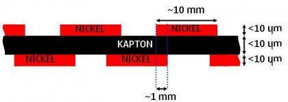
In my simulation I divided the nickel ribbon into 1 cm tall horizontal stripes like shown in the attached picture. Sides of the ribbon is glued on the speaker panel and each stripe is connected together with a solderd wire. They form 200 stripes and 199 wires in series so that the same current flows 200 times throught the same ribbon. That´s it.
I simulated how this laminate works and it works fine. 200 x 10 um gap between nickel stripes don´t decrease much magnetic flux density if stripes are a bit interleaved. 1 mm in this simulation. Magnetic flux is over 1.5T in the whole ribbon! Practically saturation flux density in nickel. WOW
What if we have long ribbon 200 x 2 cm and rotate magnetic flux and current 90 degree? So magnetic field is vertical and current horizontal
With a nickel ribbon you can do it !!!
Magnetic flux flows the whole 200 cm from up to down in the nickel ribbon and is looped back in an iron rod. There is only one relative small magnet in the loop somewhere. Can be neodym or ferrite. Total loop length is about 4 m but the single magned is enough since in the ribbon the area is really small. Only 2 cm x 10 um.
Imagine: You need only one cheap magnet !!! Total magnetic flux is only about 1/100 than needed with traditional ribbon. Sounds cheap. You cannot do that with an air gap. With a ferromagnetic ribbon you can.
But then again... current should be the same ~100 times larger if same sensitivity is needed. How to do that?
In my simulation I divided the nickel ribbon into 1 cm tall horizontal stripes like shown in the attached picture. Sides of the ribbon is glued on the speaker panel and each stripe is connected together with a solderd wire. They form 200 stripes and 199 wires in series so that the same current flows 200 times throught the same ribbon. That´s it.
I simulated how this laminate works and it works fine. 200 x 10 um gap between nickel stripes don´t decrease much magnetic flux density if stripes are a bit interleaved. 1 mm in this simulation. Magnetic flux is over 1.5T in the whole ribbon! Practically saturation flux density in nickel. WOW
Attachments
Unfortunately induced flux in the ribbon has nothing to do with the net body force from the current
I don't expect to see a bar magnet move around when I put a current thru it (assuming symmetric current return)
I believe you will find that the Lorentz force on a hi perm ribbon is little different from a low perm ribbon, the "increased field" force on the electrons inside the high perm ribbon only cause some current crowding ~= asymmetric skin effect but no net body force
also I think we call it a diaphragm or planar design when the edges are glued, a true ribbon is only supported at the ends
jcx said:
I believe you will find that the Lorentz force on a hi perm ribbon is little different from a low perm ribbon, the "increased field" force on the electrons inside the high perm ribbon only cause some current crowding ~= asymmetric skin effect but no net body force
Sad but true...
During few night I fiqured it out. If you could use planar magnetic to move it´s own magnetic field then you would have either perpetual motion machine or anti-gravitation device.
So much about this thread. But if anyone find out any real usage for ferromagnetic foil then please speak up
gl said:Hi jcx,
The Magnepan "true ribbon" is supported by alternating dots of adhesive at intervals along the edges in addition to usual support at the ends. Maybe it's a special case because of its length.
Cheers.
Graeme
Fwiw, they follow in others footsteps.
The Decca ribbons were supplied with some heavy silicone grease type "goo" that was intended to be applied on either side of the ribbon at approximately 1/3 down and 2/3 down the length of the ribbon.
I suspect that the main intent was to limit certain nasty nodes/standing waves and to prevent over excursion if hit with too much LF...
_-_-bear

- Status
- This old topic is closed. If you want to reopen this topic, contact a moderator using the "Report Post" button.
- Home
- Loudspeakers
- Planars & Exotics
- Nickel ribbon