A measurement from lug to lug would work too.
There's an offset, and I'm trying to align the poles.
There's an offset, and I'm trying to align the poles.
A measurement from lug to lug would work too.
There's an offset, and I'm trying to align the poles.
Yes, I see your problem, they don't specify the angle. About all you can do is eyeball it.
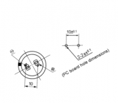
According to the datasheet you linked, the terminals are spaced 10 mm apart (i.e., a mounting circle with 5 mm radius), centered on the case diameter. What is there to "align"? The recommended mounting holes are 2.2 mm dia (0.087"), and the largest dimension of the terminal lugs is 1.5 mm (0.059") so there is 0.7 mm (over 0.025") of play between the terminals and their mounting holes - plenty of clearance to let the cap squirm around quite a bit during placement. (In fact, if I was laying out a PWB I'd look at the possibility of reducing the mounting hole size - especially if I was placing the caps manually rather than auto insertion equipment.)
Dale
Dale
Last edited:
Some datasheets give the "angle" of the holes in their working drawings. (i.e. angle in relation to the (-) label I think, i.e. after the capacitor has been twisted/inserted into the hole). Check out Panasonic datasheets, the angle is probably the same as Nichicons.What is there to "align"?
sample: http://pdf1.alldatasheet.com/datasheet-pdf/view/356852/PANASONIC/ECEC2CB471BJ.html
Last edited:
I built an F5 board, and I think the poles were correct. I know the PSU for it was intended for use with panasonics, but the Nichicons fit too.
Good thinking!
Good thinking!
I don't see any angles specified on the datasheet you linked (see atch), though drawing details have been known to hide from my tri-focaled, superannuated eyeballs. It looks like that Panasonic datasheet has essentially the same sketch for the PWB layout detail as the sketch on the OP's Nichicon datasheet.Some datasheets give the "angle" of the holes in their working drawings. (i.e. angle in relation to the (-) label I think, i.e. after the capacitor has been twisted/inserted into the hole). Check out Panasonic datasheets, the angle is probably the same as Nichicons.
sample: ECEC2CB471BJ pdf, ECEC2CB471BJ description, ECEC2CB471BJ datasheets, ECEC2CB471BJ view ::: ALLDATASHEET :::
The polarity marking on the capacitor's external insulating sleeve would ideally have a zero degree angle with respect to the associated connection pin (the " - " pin in this case). But it doesn't require very precise placement to be effective - I'd estimate that a +/- 10 degree variation from that ideal would hardly be noticed unless you were specifically looking for the variation.
Would it help the OP if the PWB layout detail sketch was shown as in the second atch file? It implies that the polarity marking band, the connection pins, and the center of the capacitor package fall along a common (horizontal, in this image) line. (If you really MUST know, I used Microsoft Photo Editor to rotate the original sketch by 29 degrees.)
Dale
Attachments
Last edited:
- Status
- Not open for further replies.
- Home
- Design & Build
- Construction Tips
- Nichicon Snap Cap PCB hole sizing and spacing