Hi All,
This is what I’m planing to do as a mono block version. Has anybody try those component values. I expect to have very small output DC offset and also the input cap (C4) is quite small. I’m thinking of doing P-to-P 3D connection instead PCB for more compact configuration (I think the original is like that too). The RC LPF will be mounted strait on the RCA connectors or omitted totally, and the Zobel is mounted on the speaker connector. The POT and 2-WAY switch are next to each other, S1 is a normal toggle switch.
Any comments would be appreciated.
Greg
Attachments
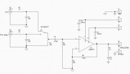
I would decrease the values of your resistors for feedback, these do not set the input impedance like in inverted setup so lower values will just result in less noise.
Thanks for the note. I agree with you for the noise level, but in order to keep the output DC offset low and the input impedance reasonably high (I need 20k) and not use NFB cap R4=R5|| R6 which is almost =R5 in my case. At the same time I need gain of 20. I hope the noise won’t be any worse than the IGC with 220k FB resistor. People that build that one don’t complain about high noise levels. But it’s yet to be proven in my case.
Hi, if you want to minimise the DC offset at the output, it is R4 and R6 that need to be equal in value, so witht his in mind, you can reduce the value of your feedback resistors, whils putting your input impeedance up. So you end up with the best of both worlds.
Andrew.
edit:
just realised that might not be entirely true as you have no dc blocking capacitor to ground after R5, so I think what I just said may not apply in this case, but I'm still not too sure.
Perhaps someone more knowledgeable about these things could tell you.
Andrew.
edit:
just realised that might not be entirely true as you have no dc blocking capacitor to ground after R5, so I think what I just said may not apply in this case, but I'm still not too sure.
Perhaps someone more knowledgeable about these things could tell you.
You would be correct if I had a capacitor in series with R5. In my case the Ib comes from GND through R5 and from the out through R6 into the -In of the amp. The out of the amp has almost the GND potential, and I need to set the gain at 20. It means R5 has to be 20 times smaller than R6. And as such R5 has 20 times more influence on Ib and the offset than R6.
The best value for R4 in my case is 21k. So I may go to 21k but I wanted to have less number of different parts.
Check the guts of the LM3875 spec sheet.
The best value for R4 in my case is 21k. So I may go to 21k but I wanted to have less number of different parts.
Check the guts of the LM3875 spec sheet.
I guess I was typing at the same time you were. I wouldn't have replied to your comment otherwise.
Thanks!
Thanks!
no wories, I have myself just sent off a PCB to be made ofr a non-inverting design, but as I had the cap in there I could keep the resistor values quite low whilst having a high input impedance. Pehaps in the future I might try this approach and see what sounds more interesting. Or, perhaps adding a buffer in front, so that a low input for the 3875 can be converted to a higher impedance for the device as a whole?
So much to try...
So much to try...
You are right.
I subscribe to the “Less is More” theory. After my experience with my Yamaha Power amp
(http://www.diyaudio.com/forums/showthread.php?postid=254246#post254246)I’m convinced that adding more on the way of the signal asks for more trouble. So in my case I’d rather use NIGC and add a small cap then add a whole buffer stage that’ll have bunch of other components. Can you imagine if you have to experiment with the “sound” of all those additional components? I get scared when I think of it.
- Status
- Not open for further replies.
- Home
- Amplifiers
- Chip Amps
- NI GC schematic. Please comment