Hi
I have a NFJ & FX-audio tube amp, the one with a cd and phono input
One day I was trying some new power tubes and fried two resistors right next to the tube sockets
Can anyone help me find a schematic showing all the resistors I can’t find one and all the pictures are fine don’t show any of the resistors that are right next to the tube sockets
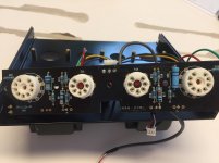
Here’s a pic of the amp. Later I’ll take some pics of the fried parts


I have a NFJ & FX-audio tube amp, the one with a cd and phono input
One day I was trying some new power tubes and fried two resistors right next to the tube sockets
Can anyone help me find a schematic showing all the resistors I can’t find one and all the pictures are fine don’t show any of the resistors that are right next to the tube sockets
Here’s a pic of the amp. Later I’ll take some pics of the fried parts
NFJ & FX-audio tube amp repair
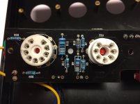
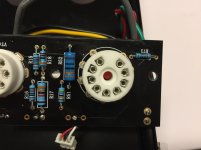
Here’s the burnt parts
R75 and R35 are the two burnt resistors


Here’s the burnt parts
R75 and R35 are the two burnt resistors
One at a time, carefully remove the damaged parts. As heat rises, maybe you'll get lucky and the color code will be intact enough to read on what's now out of sight.
Both R looks to be connected to pin 9 of the 6P1P. Pins 9 is G2. The value of that resistor is less critical. How many wires does the output transformer preliminary side has (the wire that are not connected to any speaker terminals). If it is has three wires I would put in 500R to 1K. If 2 wires I would consider 1K to 2K. If you have no idea, try 1K.
One day I was trying some new power tubes and fried two resistors right next to the tube sockets
When you say "new" power tubes, what exactly are they?
jeff
I was trying to ( roll tubes) and this little guy did not like it. I grabbed the wrong tube and as soon as I turned on the power. , smoke and a nice spark. Lol
I have the same amplifier on the bench with another kind of issue (loud background hiss that starts and stops randomly - maybe a HF oscillation). I attach the picture I made when I disassembled it for the preliminary inspection. I will resume the repair next week, at that time I will open the amplifier again and I will measure the resistors while tracing the schematic.
I suggest to be careful on tube rolling on this amplifier. It does have minimal protection on the switched mode power supply and the microprocessor may be damaged easily.
Edit: I checked your picture more carefully, and I now have a confirmation of the hypotesis I made during the disassembly: on my specimen, the value of R52 is wrong. They fitted a resistor that should have been on the motherboard instead. There are 3 QC passed stamps on this amplifier, I wonder what kind of quality control they do.
Attachments
Last edited:

Thank you very much. Mine has always been very quiet. I’ve had it running 4 different types of Klipsch speakers and never had any noise from mine. Anyway
It was a pretty cheap cost wise so no end of the world if it’s toasted
I can take better pics if that helps with yours
It was a pretty cheap cost wise so no end of the world if it’s toasted
I can take better pics if that helps with yours
The value of R35 and R73 on my board is 2k.
I exchanged the wrong R52 resistor but I still get the hissing noise. Could you please take a picture of the board (maybe splitted on right half - left half) with good lighting so I can read the value of all resistors? Maybe R52 is not the only wrong one on my specimen.
I exchanged the wrong R52 resistor but I still get the hissing noise. Could you please take a picture of the board (maybe splitted on right half - left half) with good lighting so I can read the value of all resistors? Maybe R52 is not the only wrong one on my specimen.
I was trying to ( roll tubes) and this little guy did not like it. I grabbed the wrong tube and as soon as I turned on the power. , smoke and a nice spark. Lol
Yeah, that's what I figured happened.
jeff


I could use a better close up of the R73 and the R35, if you have it
I looked up a 1k resistor and they are all saying it’s 4 band color, but I can see five bands in your picture
but it’s at an angle and with the shadow so it’s difficult for me to make out the colors properly to look it up
I looked up a 1k resistor and they are all saying it’s 4 band color, but I can see five bands in your picture
but it’s at an angle and with the shadow so it’s difficult for me to make out the colors properly to look it up
- Home
- Amplifiers
- Tubes / Valves
- NFJ & FX-audio tube amp repair