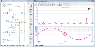
Vbe Multiplier has strong local negative feedback, and it is stable without extra compensation if the local loop involves only 2 or less components.
How about use its feedback to correct crossover distortion?
It looks pretty good.
1. Get DC feedback from Re. No more thermal runaway.
2. Get AC feedback from the output. Crossover distortion is minimized before global feedback is applied.

The output stage is biased at 83mA
How about use its feedback to correct crossover distortion?
It looks pretty good.
1. Get DC feedback from Re. No more thermal runaway.
2. Get AC feedback from the output. Crossover distortion is minimized before global feedback is applied.
The output stage is biased at 83mA
That looks pretty clever, like a cross between CFP/Renardson output stage at low frequency and the VBE multiplier feedback output stage. Do you have any insights into the thermal stability of the bias?
Hi, mazurek,
The idea is to keep the voltage drop on Re constant. With the help of of the ideal DC sources in my diagram, the voltage drop on Re is constant regardless the change of Vbe on the output transistors. Thus, it is thermal stable, even without thermal compensation.
Those ideal DC sources can be replaced with a single adjustable Vbe multiplier.
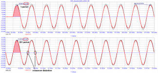
After I played around in simulation with this. This arrangement tends to transit into pure class B operations under the load. The reason is it senses big voltage drop on Re under the load. With the local feedback, it clamps bias into class B.
I haven’t find a good solution yet.
The good news is, under strong local feedback around output transistors, even driven into pure class B, the distortion is still low.
Last edited:
Good idea!
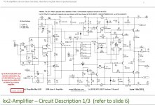
I think I see some similarity to Bonsai's SX/KX amp sensing the Re voltages (it is simpler though). It works well for keeping constant (high) DC bias without thermal coupling.
http://hifisonix.com/wordpress/wp-content/uploads/2021/06/kx2-Amplifier-June-13-2021.pdf[/url
I think I see some similarity to Bonsai's SX/KX amp sensing the Re voltages (it is simpler though). It works well for keeping constant (high) DC bias without thermal coupling.
http://hifisonix.com/wordpress/wp-content/uploads/2021/06/kx2-Amplifier-June-13-2021.pdf[/url
Last edited:
Member
Joined 2009
Paid Member
Clever Circuit
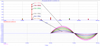
I LTSpiced this circuit. At +20dBU into 8R and 1KHz, I get THD 0.168%, with H2 at -64dB and H6 at -66dB. Into 4R, the THD increases to 1.206%, with H2 at -53dB. In both cases H2 is just dominant.
I think it has promise, but with a simple diamond buffer hybridised with a CFP and at the same 4R load, the THD is 0.0388%, which is 31 times less distortion.
The DF/CFP hybrid has H2 at -93dB and H5 at -77dB, so it's not so wonderful either.
HD
Thanks for checking this.
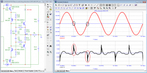
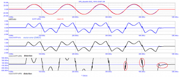
This circuitry cannot hold the bias under the load. The 2 big caps have difficulty to discharge. The bias drifts into pure class b under the load.
I also simulated with these 2 big caps removed. It is no better than a simple CFP without those caps.
Member
Joined 2009
Paid Member
Who cares if it is Class B if the distortion is still low, it is still interesting and may sound good, it might be combined with ClassA in a Quad-feedforward arrangement too. But can it drive a real speaker load? Does this make the distortion worse?
I think it is fine even without the bias.
There was a time, I biased a blameless style amplifier with 0 mA. Even though, I could not hear any artifacts/distortions.
However, I know a class A amp can easily reach -90dB THD@10Khz. For an optimized class B amp, it could be -80dB THD@10khz. They are all below the threshold that I can tell them apart.
Last edited:
any news ?Good idea!
I think I see some similarity to Bonsai's SX/KX amp sensing the Re voltages (it is simpler though). It works well for keeping constant (high) DC bias without thermal coupling.
http://hifisonix.com/wordpress/wp-content/uploads/2021/06/kx2-Amplifier-June-13-2021.pdf[/url
this URL is dead and not available by web archive. Who can upload this PDF ?
The links are there:any news ?
this URL is dead and not available by web archive. Who can upload this PDF ?
http://hifisonix.com/hifisonix-kx-amplifier-v2/
https://www.diyaudio.com/community/threads/hifisonix-kx-amplifier.329814/
He's looking for the PDF http://hifisonix.com/wordpress/wp-content/uploads/2021/06/kx2-Amplifier-June-13-2021.pdf and it is not there.The links are there:
It may have been superseeded by the Jan 2002 revision, https://hifisonix.com/wordpress/wp-content/uploads/2022/01/kx2-Amplifier-Jan-2022.pdf
Bonsai is a frequent poster here.
Well, they are the same thatHe's looking for the PDF http://hifisonix.com/wordpress/wp-content/uploads/2021/06/kx2-Amplifier-June-13-2021.pdf and it is not there.
It may have been superseeded by the Jan 2002 revision, https://hifisonix.com/wordpress/wp-content/uploads/2022/01/kx2-Amplifier-Jan-2022.pdf
Bonsai is a frequent poster here.
https://hifisonix.com/wordpress/wp-content/uploads/2022/01/kx2-Amplifier-Jan-2022.pdf
and
the dowload in the lianked: http://hifisonix.com/hifisonix-kx-amplifier-v2/
Mayby, here is the versions in June 12th 2021:
Attachments
Last edited:
Vbe Multiplier has strong local negative feedback, and it is stable without extra compensation if the local loop involves only 2 or less components.
How about use its feedback to correct crossover distortion?
It looks pretty good.
1. Get DC feedback from Re. No more thermal runaway.
2. Get AC feedback from the output. Crossover distortion is minimized before global feedback is applied.
View attachment 978564
The output stage is biased at 83mA
A specially designed harmonizer?
Attachments
It is interesting.
Circuit in OP
My simulation under 8r load similar as post #8 around .1% distortion
Using ideal and non ideal current sources and voltage sources.
To make somewhat of a real working model.
Bias is jumpy and raising output device temperature
bias is even more jumpy royal mess.
Small temp changes of other devices huge bias jumps low and high
looks cool, otherwise annoying
- Home
- Amplifiers
- Solid State
- NFB with Vbe Multiplier, Better Than CFP?