Good morning,
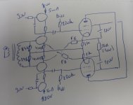
Yesterday I assembled this OTL circlotron. The tubes are 17KV6 (beam power tube) biased at about 100mA (circa -25V at their grids), the lower FETS are IXTP08N100D2 (depletion, 1000V), the top fets are STF3NK80Z (enhancement, 800V). The input transformer is a LL1540, wired for 1:1. Even though all power supplies are 180V, they are all independent (one for the driver stage, two floating for the output stage).
To test the distortion performance with my SE interface I used a 10k:600R (big) interstage transformer, with the primary wired across the 56R load resistor, and one side of the secondary grounded, other side to audio interface.
First try was without the FB resistors. The gain was about 100x, and the THD (measured with ARTA) was 1.3% @ ~2W (actually 9V RMS in the 56 ohm load). Output at about 10% THD was circa 20W. I found these results quite encouraging.
Then I applied feedback, cross-coupled because of the phase, with 2x 30k resistors. The gain decreased, confirming negative feedback, less noise (less modulation with the 1kHz fundamental), but the bad part, THD increased! I tested lower values of FB resistors, the gain decreased further (I went as low as 10x gain), but the distortion kept increasing. With most NFB I measured about 3% THD at about 1W output power.
How can that be: NFB increasing the THD?
Tinkering about it this morning: the drivers need to provide more gain to be able to apply the feedback. Maybe the distortion comes from there? I have not measured the distortion from this specific driver stage, but a previous driver stage with a gyrator loaded 1000V depletion unit powered with 400V DC gave 80VRMS at 1%THD (and a gain of about 2600x).
Departing from the 2W@1.3% THD without feedback I do think this amp has potential for good performance, so I will insist in this a bit more, and I am thankful for your comments in how to achieve this better performance.
Attachments
I think it must be something with the combination of the 1k cathode to ground, the FB resistor, and the 400R source resistors that is not working nicely together, but I do not know what. Terminating the 1k directly in the source of the driver fets would be too much feedback, so I am thinking about splitting the 400R source resistor in two series connected resistors, and terminate the 1k in the "tap".
Perhaps the feedback resistors are affecting the bias voltage of the input stages.
Output cathode DC volts goes through the feedback resistor and is applied to the feedback node of the input device.
Yes?
No?
The lower the resistance is of the feedback resistor, the more affect the DC volts of the cathode has on the bias voltage of the input stage.
Output cathode DC volts goes through the feedback resistor and is applied to the feedback node of the input device.
Yes?
No?
The lower the resistance is of the feedback resistor, the more affect the DC volts of the cathode has on the bias voltage of the input stage.
Always 6A3sUMMER coming to the rescue, many thanks!
I kept a look at the voltage over that 400R resistor (I had a DVM connected throughout the tests measuring DC) and I did not perceive a "big" chang, as it was always around 2.1VDC, so max possible change would be a couple of mV.
Erik
I kept a look at the voltage over that 400R resistor (I had a DVM connected throughout the tests measuring DC) and I did not perceive a "big" chang, as it was always around 2.1VDC, so max possible change would be a couple of mV.
Erik
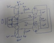
In fact you have two amplifiers with a common load and a (allmost, the two 24k tolerance) same input.
By cross coupling the FB the distortion of one side is added to the other side, not substracted.
Try it like this, with FB resistors of 270k for a gain of 10x.
And put some overvoltage protection on the input.
Mona
By cross coupling the FB the distortion of one side is added to the other side, not substracted.
Try it like this, with FB resistors of 270k for a gain of 10x.
And put some overvoltage protection on the input.
Mona
Attachments
Many thanks for the explanation Mona, looking at my old schematic it does indeed make sense!
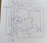
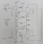
Still I chose another option for applying the feedback without having to go with cross-coupling, by taking the feedback from the plate to the driver source: schematic of my current test jig is attached.
Input is still with a transformer and the 2x 24k resistors. With a 1,5V alkaline battery I applied a bit of bias, so that the depletion fets still pass about 5mA, because the 47k resistors from plate to source pass about 4mA now. I see I forgot to draw the bias resistors to the grids of the output tubes.
With the current setup ommiting the plate to source resistors (so no feedback) I get about 1W@2%THD, and a gain of about 400x. I tried some resistors and settled for the 47k, as the gain is now about 100x - as would be expected 🙂 - and the 1W@0.3%THD (with a bit more 2nd than 3rd), and circa 20W@2%THD (a lot of higher harmonics there...).
Attachments
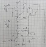
Another plan I had to avoid the cross-coupling.
The LL1540 has two separate secondary windings, so the attached schematic would be feasible. The two cathode resistors on the output tubes would need to be something as 1k and 10R, but could be AOT. The load is not drawn, but would be taken at the cathodes.
Best regards, Erik
The LL1540 has two separate secondary windings, so the attached schematic would be feasible. The two cathode resistors on the output tubes would need to be something as 1k and 10R, but could be AOT. The load is not drawn, but would be taken at the cathodes.
Best regards, Erik
Attachments
I believe Mona was right. Good!
The straightforward and effective solution is what she drew up.
I did not even do the most fundamental check of the feedback phase. My bad.
Now, we should not fall in love with 'cross coupling' just because we sometimes can employ that technique.
Cross coupling looks nice on a schematic, but may not be the best way to do things, even if the phase is correct.
I think we can consider things like transformers, chokes, etc.
Looks nice. But . . .
What is the performance of an inexpensive transformer or choke?
What is the price $$$ of a very good performing transformer or choke?
Can another topology perform just as well if it does not use a transformer or choke?
Yes, I very much like power transformers, not switchers; output transformers, not OTL; and B+ filter chokes, instead of a resistor between the first 2 B+ caps; or in the case of choke input filter, just before the first B+ cap. And choke input filter is my favorite versus the cap input filter (if I have the B+ secondary that will give the B+ volts I want with the consequential secondary Vrms x 0.9 choke input = DCV out factor.
(Even though I have used interstage transformers, phase splitter chokes, and choke plate loads).
I just have my own preferences as to how and where to use a transformer or a choke.
I do need to get busy soldering that chassis - it is waiting to become a balanced amplifier.
The XLR connector is mounted, and the other parts are there; the CD player with the balanced XLR outputs is waiting too. There is no need for an input phase splitter transformer in this new system.
Last edited:
That's a nice idea ! You could call it a modified Schade feedback.Another plan I had to avoid the cross-coupling.
The LL1540 has two separate secondary windings, so the attached schematic would be feasible. The two cathode resistors on the output tubes would need to be something as 1k and 10R, but could be AOT. The load is not drawn, but would be taken at the cathodes.
Best regards, Erik
Mona
Cross coupling does indeed sound fancy, but was necessary to get the phases right, so feedback would be negative. In the end I am happy it works without it!I believe Mona was right. Good!
The straightforward and effective solution is what she drew up.
I did not even do the most fundamental check of the feedback phase. My bad.
Now, we should not fall in love with 'cross coupling' just because we sometimes can employ that technique.
Cross coupling looks nice on a schematic, but may not be the best way to do things, even if the phase is correct.
I think we can consider things like transformers, chokes, etc.
Looks nice. But . . .
What is the performance of an inexpensive transformer or choke?
What is the price $$$ of a very good performing transformer or choke?
Can another topology perform just as well if it does not use a transformer or choke?
Yes, I very much like power transformers, not switchers; output transformers, not OTL; and B+ filter chokes, instead of a resistor between the first 2 B+ caps; or in the case of choke input filter, just before the first B+ cap. And choke input filter is my favorite versus the cap input filter (if I have the B+ secondary that will give the B+ volts I want with the consequential secondary Vrms x 0.9 choke input = DCV out factor.
(Even though I have used interstage transformers, phase splitter chokes, and choke plate loads).
I just have my own preferences as to how and where to use a transformer or a choke.
I do need to get busy soldering that chassis - it is waiting to become a balanced amplifier.
The XLR connector is mounted, and the other parts are there; the CD player with the balanced XLR outputs is waiting too. There is no need for an input phase splitter transformer in this new system.
On the net I found this https://www.tubecad.com/december2000/page14.html and some other people that used this as a basis, that is the reason for tryuing the cross coupling. Probably this idea from Broskie would not work in real life.
I have a nice workbench with a lot of adjustable power supplies, so lately I have been prototyping all sort of amplifier stages. A2 with 811, PP with Rl15a, SPUD with E130L, GU50SE, etc etc. It is relatively fast. The problem is to make these into "stand alone" units (get all the necessary voltages from the PS, exact heater voltages...) that I can actually carry to the living room to listen on my main speakers (that are the ones that can be wired for 56R on the bass, and 72R for mid and high).
I finished a pair of SE amps with GM70, my first experience close to 1000VDC. Very conventional: big Sowter OPT, doubler with MKP capacitors and Hammond choke, DC with CCS on the GM70s. These are staying in the basement, where I have my workshop and a mono line array. They are nice!
Erik
Last edited:
Indeed the inspiration is from the original Schade schematic, from 1938. I think I will try it out, it looks so "minimalistic", but I think it has potential!That's a nice idea ! You could call it a modified Schade feedback.
Mona
In case you use a singe tranformer with 2 secondaries there will be coupling between the 2 secondaries (1:1)
Now you mentioned it, this is indeed true, and probably why it did not work during my tests yesterday evening, where I had the same issues: applying feedback reduced the gain, but increased the distortion.In case you use a singe tranformer with 2 seconndairies there will be coupling between the 2 secondairies (1:1)
,...afterwards it is so obvious... thanks for the tip!!
So one possibility would be to use two 1:1 transformers per channel, with the primaries in parallel, and one secondary to each circlotron leg? A lot of transformers to avoid the output transformer 🙂
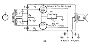
Thinking about Lampie519's post, I went back to the original Schade schematic, where the two secondaries are coupled.
I used this sort of feedback in single ended stages, where it worked very well: one side of the secondaries transformer to the grid, and feedback (From the plate) through a voltage divider to the other side. This works ok, output at the plate is clean and low distortion, while the input at the grid is high distortion, the result of the feedback correction. Can I say that the magic (adding and subtracting of distortions...) happens in the transformer?
But, how is the balanced version from Schade then supposed to work? Each output tube has its own "transfer function", which is corrected by the "magic" in the input transformer. But in Schade this happens twice, and as pointed out by Lampie519, the two "magics" are coupled, so they influence each other?
I am happy for all the smart people around here helping out, if you were not there I would still be making ECC83 + EL84s thingies 🙂
Best regards,
Erik
Attachments
Last edited:
Did you perhaps cross coupled the windings too ?Now you mentioned it, this is indeed true, and probably why it did not work during my tests yesterday evening, where I had the same issues: applying feedback reduced the gain, but increased the distortion.
It should work well, there is no question of coupling between secudairies.
The secundaires don't induce anything,there is no current only some capacitive coupling. The only current in the transtormer is the input.
Mona
True, if there is no current flow they are just floating…
But they are in a feed back or bootstrap loop depending on phase…
But they are in a feed back or bootstrap loop depending on phase…
I tried to do my very best with wiring. In the first try I shorted the 10r resistors, so no feedback. When I took the short out, the gain was reduced (and THD increased).
The schematic with the dual secondaries is actually easier to build, because from the winding through the driver to the output tube there is no crosscoupling. The only thing that is crosscoupled is the wire with B+ from G2 from one side to the plate of the other side.
I redraw the plan, and I will try it again!
Attachments
I improved the layout (shorter wires), redid the PCB with the SS driver stage, used PS decoupling caps with shorter wires... all with all, the sort of things one should do when aiming for better results. And indeed, it worked!
I used 1k+10R, so the gain for the moment is about 100x. Distortion at 1W is about 0.2%, at 12W is 0.6%. I raised the B+ supplies to 200V, and power at 0.6% went to about 20W. Afterwards hard clipping, probably to be expected.
I used 1k+10R, so the gain for the moment is about 100x. Distortion at 1W is about 0.2%, at 12W is 0.6%. I raised the B+ supplies to 200V, and power at 0.6% went to about 20W. Afterwards hard clipping, probably to be expected.
- Home
- Amplifiers
- Tubes / Valves
- NFB in circlotron. More NFB = higher THD. Why?