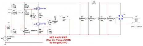
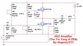
This simple single ended amplifier could serve as a complement to the well-known ZEN, both for its extreme simplicity and for its quality specifications.
As features, I can list:
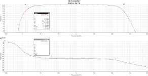
1) SNR at 1W into 8 ohms = 87.71 dB (1 KHz)
2) I bias = 1.45 A
3) Output impedance = 2.23 ohms (1 KHz)
4) Damping factor at 1 KHz and 8 ohms = 3.57
5) Voltage gain at 1KHz = 12.88 dB (x 4.4)
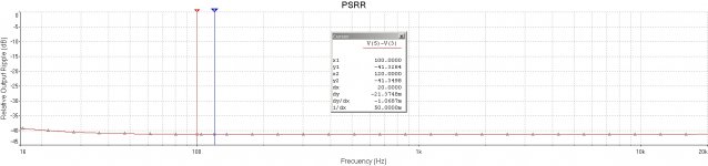
6) PSRR at 100 Hz = 41.33 dB
7) Supply voltage = 32 VCC aprox.
Two adjust: Offset ("O" trimpot) and I bías ("B" trimpot)


Best regards
As features, I can list:
1) SNR at 1W into 8 ohms = 87.71 dB (1 KHz)
2) I bias = 1.45 A
3) Output impedance = 2.23 ohms (1 KHz)
4) Damping factor at 1 KHz and 8 ohms = 3.57
5) Voltage gain at 1KHz = 12.88 dB (x 4.4)
6) PSRR at 100 Hz = 41.33 dB
7) Supply voltage = 32 VCC aprox.
Two adjust: Offset ("O" trimpot) and I bías ("B" trimpot)
Best regards
Attachments
-
 NEZ Amplifier (Schematic).jpg152.3 KB · Views: 1,184
 -
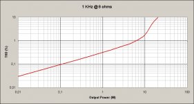 NEZ Amplifier (THD vs Output Power).jpg133.6 KB · Views: 1,121
 -
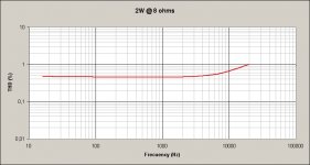 NEZ Amplifier (THD vs Frecuency) at 2W.jpg125 KB · Views: 1,121
 -
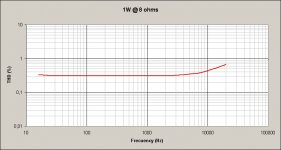 NEZ Amplifier (THD vs Frecuency) at 1W.jpg124.7 KB · Views: 1,109
 -
 NEZ Amplifier (Bode).jpg731 KB · Views: 1,090
 -
 NEZ Amplifier (PSRR).jpg231.7 KB · Views: 1,103
Last edited:
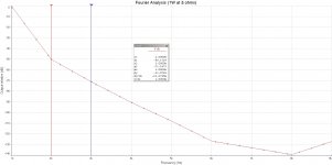
Fourier analysis (envelope of harmonic components) for 1 KHz and 1W at 8 ohms:

Best regards
Best regards
Attachments
Last edited:
Most interesting ! Well done 🙂
Also I guess many will have the same suggestions as I would about biasing of the mu-follower (why not use opto ?) and eliminating the source resistor R4.
But meantime why dont you tell us about R8, R10 and the grounding scheme ?
Also I guess many will have the same suggestions as I would about biasing of the mu-follower (why not use opto ?) and eliminating the source resistor R4.
But meantime why dont you tell us about R8, R10 and the grounding scheme ?
Last edited:
Thank you so much kasey197 !!!
Which scheme would you imagine to suppress R4?
Although the offset (V/2 point) is stable with temperature, the current bias depends somewhat on the supply voltage.
A stabilized voltage is the most advisable for this simple amplifier.
Best regards 🙂
Which scheme would you imagine to suppress R4?
Although the offset (V/2 point) is stable with temperature, the current bias depends somewhat on the supply voltage.
A stabilized voltage is the most advisable for this simple amplifier.
Best regards 🙂
The optocoupler route used in NP’s single ended amp works a treat...
Take a look at this thread for a discussion...
50w Single-Ended BAF2015 Schade Enabled
Take a look at this thread for a discussion...
50w Single-Ended BAF2015 Schade Enabled
Attachments
Which scheme would you imagine to suppress R4?
I think you could remove both R4 and R6, although increasing C1 might
be helpful. You need good heat sinking and some attention to the
bias over the first hour or so, as it heats up.
Alternatively you can suppress the action of R4 by returning the speaker
(-) to between the Source pin of Q1 and R4.
And remember to put Gate resistors on those Mosfets.....

Thank you very much, Nelson, for your wise advice and limitless generosity 🙂. I will try to implement them, to offer them for the experimentation of the diy community.
Best regards
Best regards
Hi Diego
great as always!
How does it compare to DLH ?
Can you remember me you preferred cheaper mosfet that can be used instead of the IRF150?
it was something like 055
great as always!
How does it compare to DLH ?
Can you remember me you preferred cheaper mosfet that can be used instead of the IRF150?
it was something like 055
Hi. Nice to see you here !!!. This simple amp, like the ones I generally prefer, is single ended. It's more comparable to ZEN than DLH, in many ways, just a little bit easier. With the most recent suggestions offered by Nelson Pass, you can simplify and arrive at an even more economical circuit, without appreciable deterioration of the general parameters (without R4 and R6). I was simulating the simplifications and the results are practically similar to those of the initial circuit (post 1).
Among the mosfets, a wide variety could be tested without major difficulties: IRFP150N, IRFP240N, IRFP044N, etc. Same choice as for ZEN.
Best regards 🙂
Among the mosfets, a wide variety could be tested without major difficulties: IRFP150N, IRFP240N, IRFP044N, etc. Same choice as for ZEN.
Best regards 🙂
I think you could remove both R4 and R6, although increasing C1 might
be helpful. You need good heat sinking and some attention to the
bias over the first hour or so, as it heats up.
Alternatively you can suppress the action of R4 by returning the speaker
(-) to between the Source pin of Q1 and R4.
And remember to put Gate resistors on those Mosfets.....
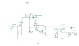
I've come up with something like this:
In this scheme, the positive change is the drop in output impedance, which goes from 2.23 ohms to 0.83 ohms, so that the DF increases from 3.57 to 9.55 (@ 1 KHz and 8 ohms).
The rest of the parameters do not change substantially.
I have omitted the gate stoppers, for clarity in the schematic. They should be no more than 470 ohms or slightly less as well.
Thank you very much Nelson!!!
Attachments
Last edited:
I believe that there will be no problems in using them 😉. The recommended heatsinks should be no more than 1 ° C / W.
Best regards
Best regards
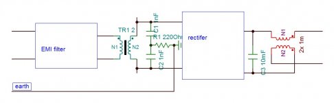
Hello Diego. About 2 years ago I did a similar circuit but in SRPP 24W. The problem I could not resolve to perfection is the power supply buzz. I was using a switching power supply that as law requires has a capacitor linking the earth to the output. As the supply is floating, this internal capacitor needs to be isolated by using not single inductance as you did but double on both poles. If you use a toroid transformer it makes the same problem. May be transformer with independent compartments is the best solution, but then it is custom made.

Hayk
Hayk
Attachments
Last edited:
Hello kokoriantz !!!. Nice to see you here. Your circuit is very interesting. Do you have any PSRR curve of your circuit to show, depending on the polarization setting that you consider convenient?
With the PSU I suggested, the noise due to ripple should be on the order of 100 uV approx.
Best regards 🙂
With the PSU I suggested, the noise due to ripple should be on the order of 100 uV approx.
Best regards 🙂
It is not the ripple the problem, The hum and buzz that gets on the secondary in reference to ground by capacitance from the primary. It acts as noise generator in parallel to the feedback shunt resistor 180 ohm in yours. Decrease to minimum you can. You need to earth the secondary wires by a pair of 1nf and resistor. The 2mH make it 2× 1mH to be on +&-. The inductor the capacitors and the resistor form a notch comes in parallel to the feedback shunt resistor.
See also the PSU of another floating supply amplifier A260. It uses a shielded transformer, and double CLC.
See also the PSU of another floating supply amplifier A260. It uses a shielded transformer, and double CLC.
Attachments
Last edited:
- Home
- Amplifiers
- Pass Labs
- NEZ Amplifier (The Yin Yang of ZEN)