For me the C3g is a very good preamp tube and C3m/C3o are the best IDHT drivers. Please read this article from Jacmusic site about C3g/ C3m. Empty Page
The optimum loading for the large midband of frequencies is no loading at all; this gives minimum distortion for the driving triode. At frequencies near the top of the transformer's range, some damping gives an advantage, for both frequency response and distortion, with the reactive (and resonant) load on the driving valve.
Jensen, for example, specifies exact values of damping Zobels, and I'll bet Dave Slagle would give you a specific recommendation if you tell him your plan and specify the output valve. He's solid and really knows his stuff.
All good fortune,
Chris
Jensen, for example, specifies exact values of damping Zobels, and I'll bet Dave Slagle would give you a specific recommendation if you tell him your plan and specify the output valve. He's solid and really knows his stuff.
All good fortune,
Chris
As Chris wrote earlier, and I also warns in #15
"Your IT hasn't correct secondary terminating. The transformed impedance at #D3a anode is indefinite, not 5k. "
must correctly load the IT.
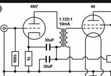
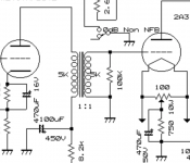
Please help with the correct secondary termination required for the IT. Should the top of the secondary tie to the bottom of the secondary with a 100K resistor in between and the bottom of the secondary tie to ground? I have found 2 different schematics for ITs and not sure which is appropriate (see attached).
Attachments
Last edited by a moderator:
Try paralleling 10k..22k resistor with IT secondary. Your reflected load to C3g anode will be - approximately - this value.
I put a 22K resistor across the IT secondary, then measured the load across the secondary/22K resistor. The resistance was 730ohms.
"I put a 22K resistor across the IT secondary, then measured the load across the secondary/22K resistor. The resistance was 730ohms. "
???
This value is the secondary DCR // 22k.
It's totally indifferent for impedance transforming to primary side.
???
This value is the secondary DCR // 22k.
It's totally indifferent for impedance transforming to primary side.
banpuku,
The need for a secondary terminating resistor is dependent on:
The make and model of the Interstage Transformer.
The plate impedance, rp, of the driver tube.
A 1:1 turns ratio often is the best behaved Interstage Transformer.
All Generalizations have exceptions.
I have designed amplifiers with some 1:1 Interstage Transformers; some 1:1.25 Interstage Transformers; and some 1:1 auto transformers (Interstage Splitter Transformers).
The impedance ratio of a transformer (for example, a 1:1.2 turns = 1:1.44 impedance ratio).
Remember, the ratio will reflect the secondary terminating resistor back to the primary, and to the driver plate.
With a 1:1.2 turns ratio, a 100K secondary terminating resistor will reflect 69.4k Ohms back to the primary, and therefore to the driver plate.
Check the sound with and without a terminating resistor; use a scope and square wave signal generator; and use your ears and music.
I have since "crossed over to the other side", I only use RC coupling now.
Some love it, some hate it, some use both RC coupling and Interstage Transformer methods.
Last edited:
An Interstage Transformer consists of the following:
Primary Inductance; Secondary Inductance
Distributed capacitance across the primary
Distributed capacitance across the secondary
Capacitance from primary to secondary
Capacitance from primary to laminations
Capacitance from secondary to laminations
Leakage Inductance (from primary to secondary)
DCR of primary
DCR of secondary
Q factors
And Resultant Phase Shifts
Laminations
Interleaved laminations (E’s and I’s), Or . . .
Air Gapped Laminations (E’s on one side, and I’s on the other side)
. . . Sorry, I will let someone else cover Toroids, C-cores, and Double C-cores)
With potential DC saturation, and Low Frequency saturation, as applicable or not.
Hmm, the above looks like like lots of:
Potential resonators,
Insertion losses,
Low frequency fall off
High frequency fall off
With proper transformer design, and proper circuit values including driver rp, terminating resistors if needed or not, etc., the Interstage Transformer works very well . . .
And the Bumble Bee can Fly
Just my opinions
Page 486 of "Magnetic Circuits and Transformers" MIT press,
interstage transformer is analyzed with secondary as opened-circuit:
For low and mid range frequency range
VSecondary/Vsource ~ (M/Lprimary) * 1/sqrt(1+(Rs/(2πf * Lprimary))^2)
M = mutual inductance
Lprimary = primary inductance
Rs = source resistance (rp) + primary resistance
For flat response, keep the ratio Rs/(2π f*Lprimary) small
by having a small Rs and large Lprimary (conflicting ?).
For higher frequency range, the effects of the capacitances
(primary shunt capacitance, interwinding capacitance, secondary capacitance) become
important....
I have pinged Dave Slagle who made my IT. He states that this specific 1:1 interstage transformer does not require any termination and any resistor placed there is a liability. So, I will leave it as is.
Meanwhile, I played around most of the day changing the operating points, RC vs. LED vs. batter bias for the C3g. In the end, I am using RC cathode bias. Sound is firmer, tighter bass, better transients and good string definition. More lifelike. C3g triode operating point is 175V, 12.5mA and -1.27V bias.
Meanwhile, I played around most of the day changing the operating points, RC vs. LED vs. batter bias for the C3g. In the end, I am using RC cathode bias. Sound is firmer, tighter bass, better transients and good string definition. More lifelike. C3g triode operating point is 175V, 12.5mA and -1.27V bias.
- Home
- Amplifiers
- Tubes / Valves
- Next steps: grid and supply chokes for C3g drives 45B